

Allplan Rebar Detailing Teams: How to Organize Layers and Project Structure Efficiently
Why layer standards matter for Allplan rebar detailing teams
Rebar detailing in Allplan can either be a smooth, efficient process or a chaotic mess. The difference lies in how well Allplan rebar detailing teams organizes its layers, drawing files and project structure. Many teams make the mistake of relying on default settings or ad-hoc systems. The result is overlapping elements, mislabeled layers, confusion in coordination, and ultimately costly errors and delays.
While Allplan provides powerful tools and flexible modeling capabilities, those tools only deliver value when used within a structured environment. That structure begins with standardized layers and drawing files. Once standardized, Allplan rebar detailing teams, work faster, reduce errors, and produce cleaner reinforcement drawings.
In NS Drafter, we most often work on pre-made project templates tailored to different countries. These template projects already contain a defined layer structure that usually just needs to be adjusted, not built from scratch.
Organize drawing files by structural components
A single drawing file containing an entire building model may seem manageable on small projects, but it quickly becomes a problem on larger ones. Navigating that model becomes slow, multiple users can’t work effectively at the same time, and exporting clean, coordinated shop drawings becomes a nightmare.
Instead, use a modular approach. Create separate drawing files for each major structural component:
Foundations
Columns
Beams
Slabs
Walls
Stairs
Name them consistently (e.g., 01_Foundations_L1, 03_Columns_L2). This helps project managers, drafters, and QA teams find what they need quickly and reduces the likelihood of modeling errors or accidental edits.
Allplan also supports several types of organizational divisions that significantly ease modeling. As the tittle suggests, having a structured project setup helps us, for instance, put vertical elements into one drawing file, and slabs into another. But we can go even further, prefabricated and monolithic columns can also be split into layers directly on the drawing sheets. There’s no hard rule for this, but effective use of structure and layers significantly eases the workflow. Whether we sort all elements by drawing files or just by layers depends entirely on the drafter.
By separating drawing files for different kind of structures, Allplan rebar detailing teams can collaborate in parallel without conflicts.
Functional layer structure for rebar detailing
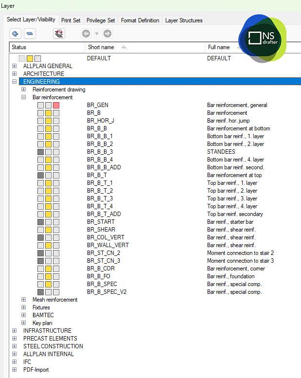
With drawing files in place, the next step is setting up layers based on the role each element plays in the reinforcement model. Clear layer definitions help organize your reinforcement logically and allow for fast selection and editing which is especially important for Allplan rebar detailing teams. The structure below represents layer groups, each divided into smaller subsets, and each subset can contain an unlimited number of individual layers depending on project needs. Maintaining a well-organized layer structure significantly improves clarity, reduces errors, and increases efficiency when working in detailing software. Suggested layer structure includes:
Architecture
Engineering
Infrastructure
Precast elements
Steel construction
Allplan Internal
IFC
PDF- Import
Annotation elements should also have their own dedicated layers:
REB_TEXT – For general notes or bar descriptions
REB_DIM – For dimensions
REB_LABELS – For mark numbers and bar tags
Personally, I prefer putting every bar “layer” into its own layer in Allplan. That way, I can quickly access and modify a specific group of bars if the client requests changes to cover, diameter, or spacing.
This structured approach provides multiple advantages:
Quicker rebar selection for editing or review
Clean isolation of specific bar types
Faster troubleshooting during QA
Reduced clutter when generating views or layouts
Without a system like this, your model becomes difficult to manage, especially as the complexity grows.
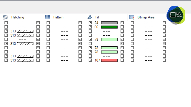
Color-coding layers in Allplan for fast QA
Color isn’t just for presentation, it’s a working tool. Layers can also be assigned pen, line, and color attributes for both on-screen display and plotting. Assign each layer a distinct color that visually communicates its purpose. This might look like:
Red for longitudinal bars
Blue for stirrups
Green for additional reinforcement
Gray for annotation
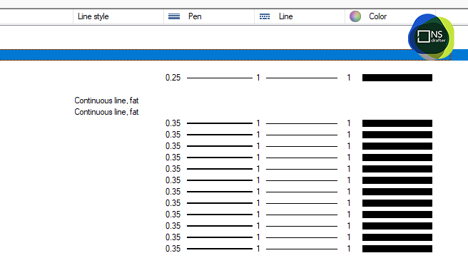
This color scheme should be standardized across your team. When used properly, color coding becomes a fast visual validation tool, helping you detect misplaced bars, missing tags, or inconsistent modeling. It also improves print clarity when generating shop drawings.
Additionally, each layer can be linked to a specific line type, which can be printed differently depending on the project phase, whether it’s for formwork, reinforcement, excavation, or layout plans.
Adopt a strict naming convention as well. Always prefix rebar layers with REB_, and avoid generic or default names like Layer1, Draft_01, or MyLayer. These create confusion, especially in multi-user environments or during handoff between teams.
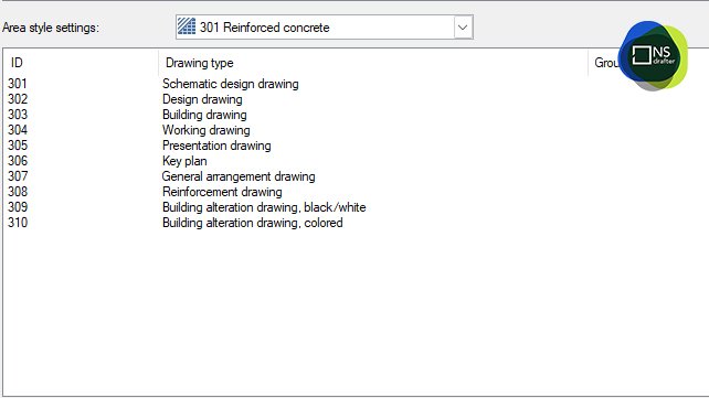
Layer organization and drawing types
In Allplan, one of the key tools for efficient work isn’t just detailing, it’s organization. You can have a perfectly modeled reinforcement layout, but without a well-structured layer system, clarity and control over your drawings can quickly be lost. That’s where the power of drawing types comes in. When layers are carefully categorized by function (e.g., longitudinal bars, transverse bars, working, transport, etc.), they can later be easily filtered, sorted, and managed using drawing types.
For example: Imagine you need to review only the longitudinal reinforcement in one wall. Instead of manually turning layers on and off, you simply activate a drawing type that displays only that layer, highlighted in red, while everything else is dimmed or hidden.
One click gives you full control over what you see.
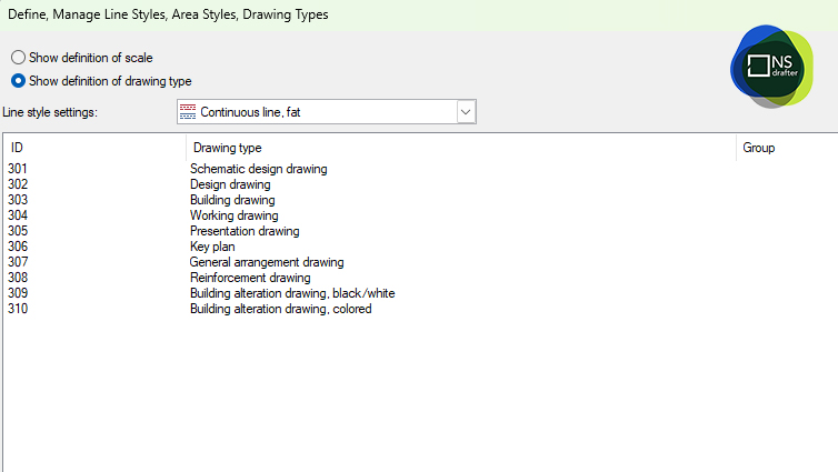
Similarly, you can prepare custom drawing types for printing, such as:
- Reinforcement in black, concrete in gray, annotations in red
- Or just texts and marks for a final QC review
All of this is only possible if your layer structure is properly set up from the start.
So it’s no exaggeration to say that a well-planned layer system and drawing types directly impacts your workflow speed, documentation clarity, and overall control throughout the detailing process.
These tools not only make daily work faster, they significantly reduce human error in modeling and documentation.
A well-structured combination of layers and drawing files allows you to quickly hide unnecessary details when creating section views. With just a few clicks, you can disable entire reinforcement zones (top or bottom) in sections where they aren’t needed. If bars are not correctly placed in layers or drawing files, each unwanted bar must be manually hidden, significantly slowing down the project.
Separate concrete from reinforcement
Another common mistake in Allplan projects is mixing concrete geometry and reinforcement on the same layers. This might seem efficient at first—but it leads to major problems down the line, especially in BIM workflows.
Instead, create a second set of structural layers for concrete elements:
CONC_BEAM
CONC_COLUMN
CONC_WALL
CONC_SLAB
With this separation, you gain several advantages:
- You can export rebar and concrete separately for use in IFC or Bimplus
- Coordination with other trades (like MEP) becomes cleaner and clash detection is more accurate
- Viewports and drawing layouts are easier to manage
Keeping rebar and structure separate is not just cleaner, it’s essential for BIM compliance and collaborative success.
Use a layer guide and project template
Once you define your layer structure, document it. Create a Layer Guide (PDF or online doc) that includes:
- The purpose of each layer
- Naming rules
- Assigned colors and line styles
- Examples of proper usage
This guide should be distributed to your entire team and incorporated into onboarding procedures. Even better, bake it into your workflow by creating an Allplan project template.
Once you create custom layers, either from scratch or based on an existing project, you can turn them into a project template and reuse them across projects. This is a fantastic solution for design offices working in a standardized environment. Once layers are set, every drawing will be printed identically.
This template should include:
- Preloaded layers – with predefined colors, line types, and pen thicknesses to ensure visual clarity and consistent output
- Drawing types – controlling how each layer is displayed or hidden in different contexts (e.g., modeling, annotation review, printing)
- Drawing files – structured by structural category (e.g., slabs, walls, foundations) to maintain project clarity and improve navigation
- Attributes – for advanced filtering, selection, and data management, allowing users to isolate elements by bar type, role, or construction phase
- Customized attributes – tailored to specific project or workflow needs
Together, these elements create a foundation for a clean and efficient detailing environment, where every bar, label, and view is easy to manage and ready for production.
With predefined project templates, Allplan rebar detailing team avoid wasting time setting up new layer systems from scratch. New users can start modeling immediately and do it right.
Conclusion
Standardizing your Allplan layer structure may take time, but the benefits compound over dozens of projects. You’ll reduce time spent on repetitive setup, minimize miscommunication, and produce cleaner, more professional shop drawings. This ensures that Allplan rebar detailing teams deliver accurate, consistent, and BIM-compliant reinforcement models across projects.
You’ll also be able to:
- Coordinate better across disciplines
- Reduce clashes and revision cycles
- Improve QA/QC for every drawing
Remember: Allplan’s power is only as strong as the structure behind it. Build that structure now, and future you (and your team) will thank you.
Frequently asked questions (FAQ)
Q: How do Allplan rebar detailing teams benefit from standardized layers?
A: Standardized layers help Allplan rebar detailing teams reduce errors, speed up modeling, and create cleaner reinforcement drawings.
Q: Why should Allplan rebar detailing teams separate concrete and reinforcement layers?
A: By separating concrete and reinforcement, Allplan rebar detailing teams achieve better BIM exports, easier clash detection, and smoother coordination with other trades.
Q: What role do templates play for Allplan rebar detailing teams?
A: Templates save setup time and ensure every project starts with the same predefined layer structure, helping Allplan rebar detailing teams maintain consistency across drawings.
Q: How do Allplan rebar detailing teams use drawing types?
A: Allplan rebar detailing teams use drawing types as a powerful way to control visibility, color, and print behavior of elements within a project, especially when dealing with complex reinforcement models.
Q: Why is color coding important for Allplan rebar detailing teams?
A: Color coding allows Allplan rebar detailing teams to visually validate reinforcement placement, detect errors faster, and produce clearer shop drawings.
