

Successful Construction Case Study I 60 000 m² in Laykovo
The Starting Point: AutoCAD Files, PDF Drawings, and a Lot of Questions
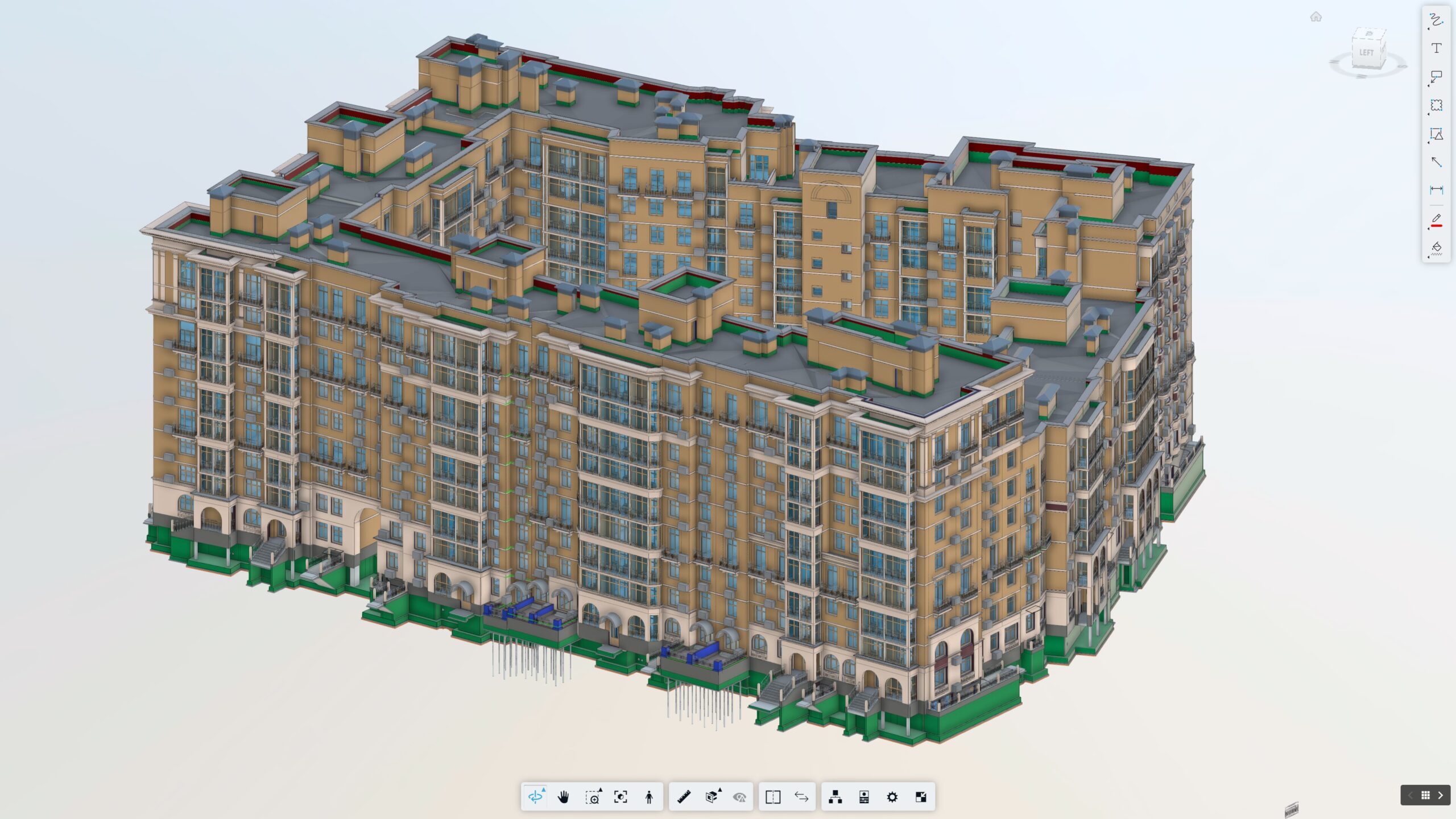
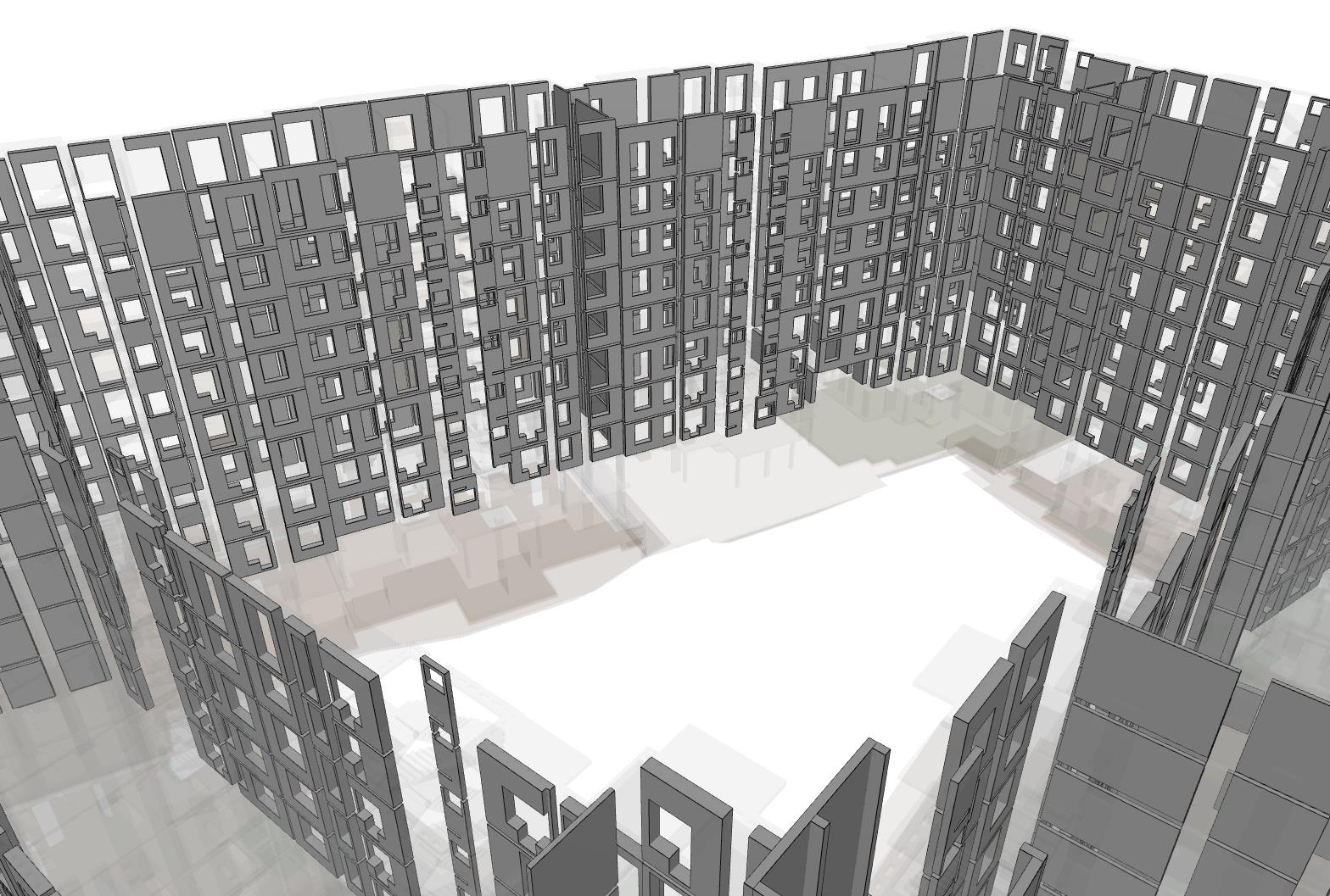
NS Drafter was engaged to deliver a complete BIM model covering three disciplines: Architecture, Structure, and MEP for a large residential complex. The project consisted of multiple buildings and shared infrastructure spread across approximately 60,000 square meters of floor area.
The input documentation consisted of AutoCAD DWG files and PDF drawings. In theory, this is standard. In practice, the documentation was partially incomplete, and significant portions contained discrepancies between files – dimensions that didn’t match between plans and sections, MEP systems that appeared in one drawing set but not another, structural details that conflicted with architectural layouts.
Key challenge: Incomplete and inconsistent input documentation is one of the most common, and most costly realities of large-scale residential construction projects. A BIM model built on bad input data produces a bad model. Our first task was documentation review.
Scope of Work
The phrase “BIM model” covers a very wide range of deliverables. At LOD 300/350, every modeled element contains geometric accuracy sufficient for coordination, plus parametric data sufficient for quantity takeoff and cost analysis. Everything is intentional.
Structure
Architecture

MEP BIM Modeling (HVAC & Plumbing)
MEP (Electrical)
MEP (Fire Suppression)
Individual apartments were modeled at the structural and partition level.
Finish layers inside private units were deliberately excluded, as these are typically completed by individual owners after handover which is a standard practice for this type of residential construction.
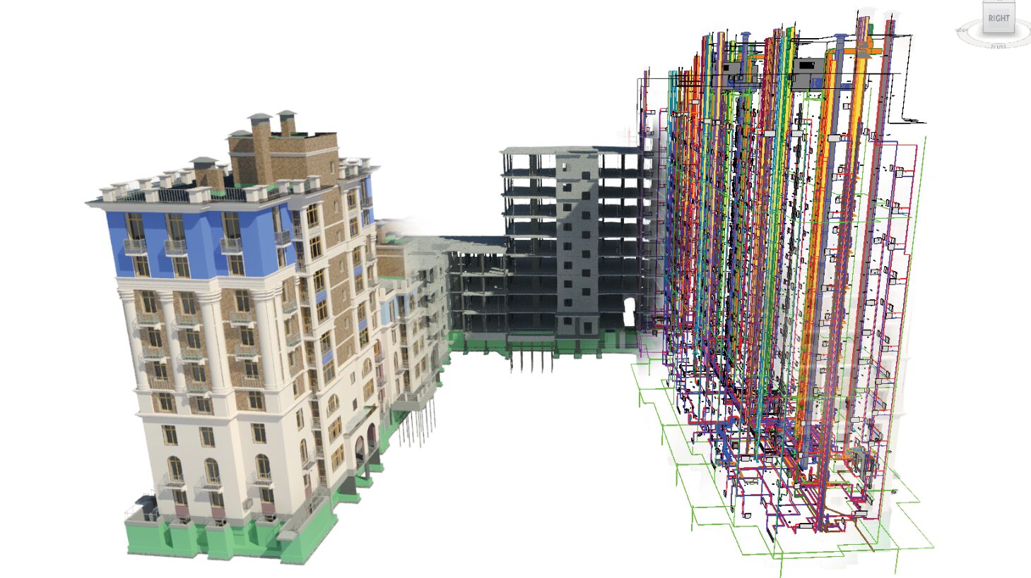
The Basement: Where All Systems Converge
If there is one space that tests the quality of a BIM model, it’s the basement.
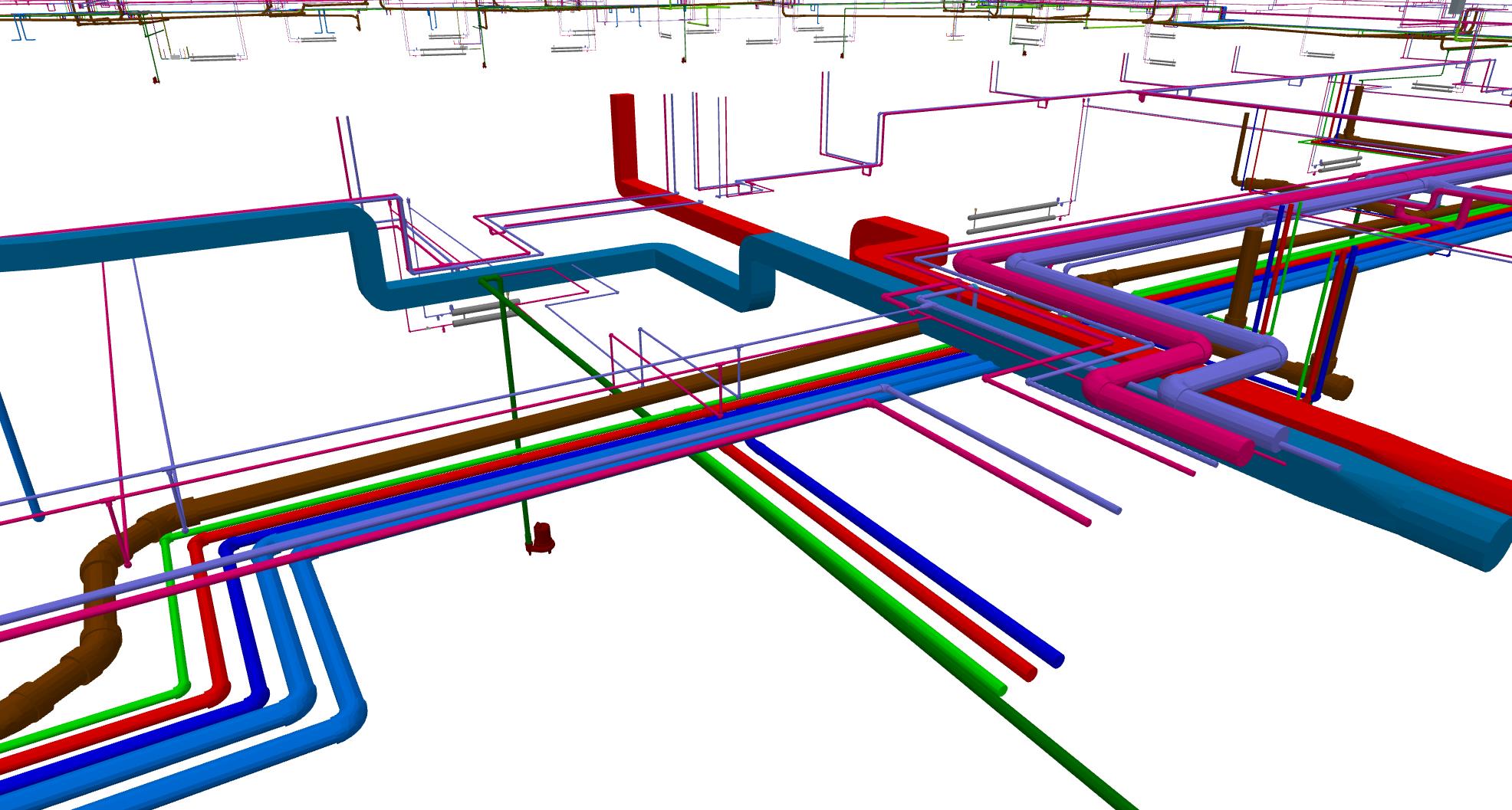
Every vertical system terminates, connects, or passes through it. Structural foundations occupy the same floor plane as MEP distribution headers. The district heat substation sits alongside plumbing risers, drainage pumps, electrical panels, cable trays, and ventilation intakes, in a space where headroom is already tight.
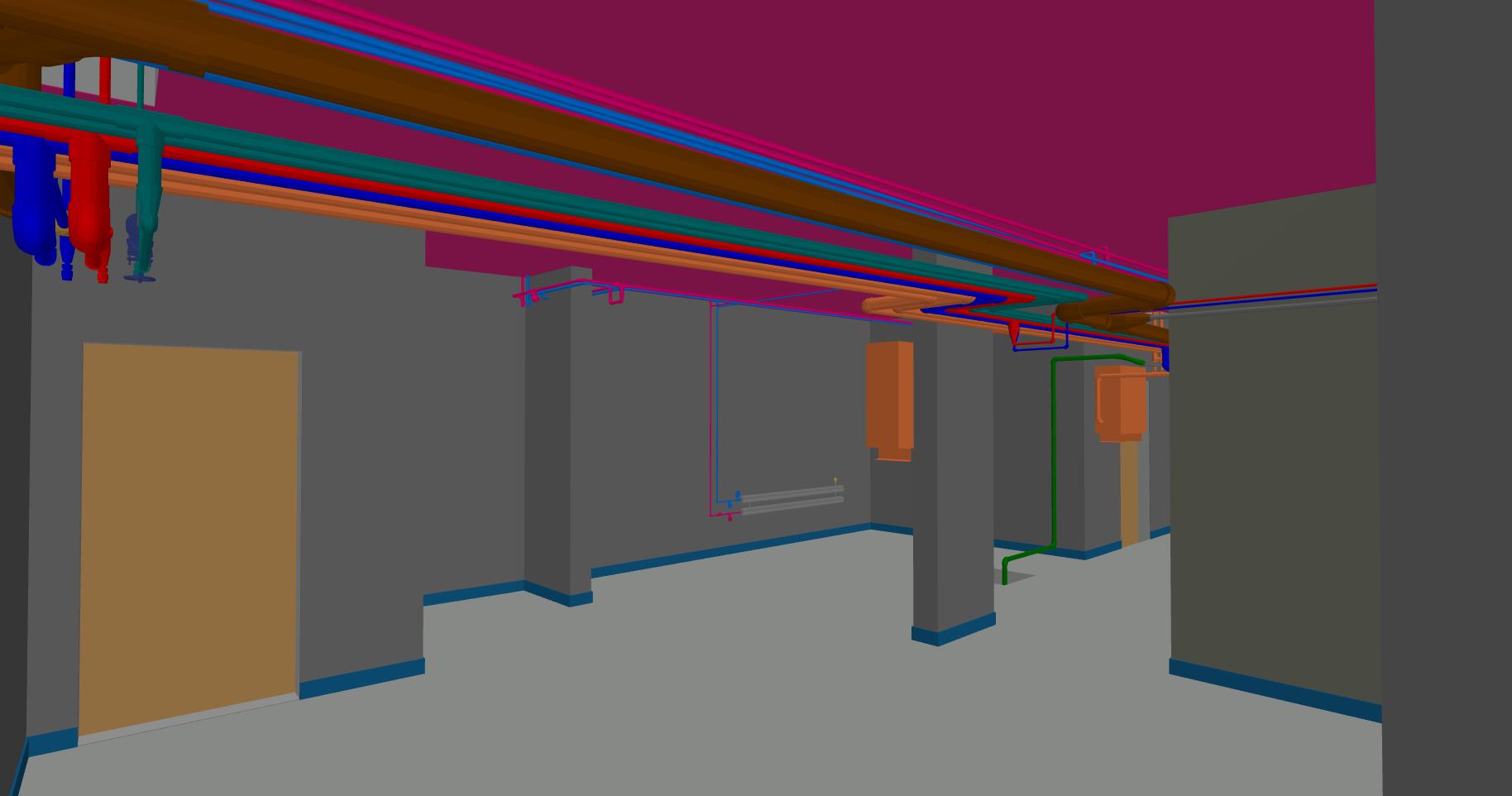
On this project, the basement model included:
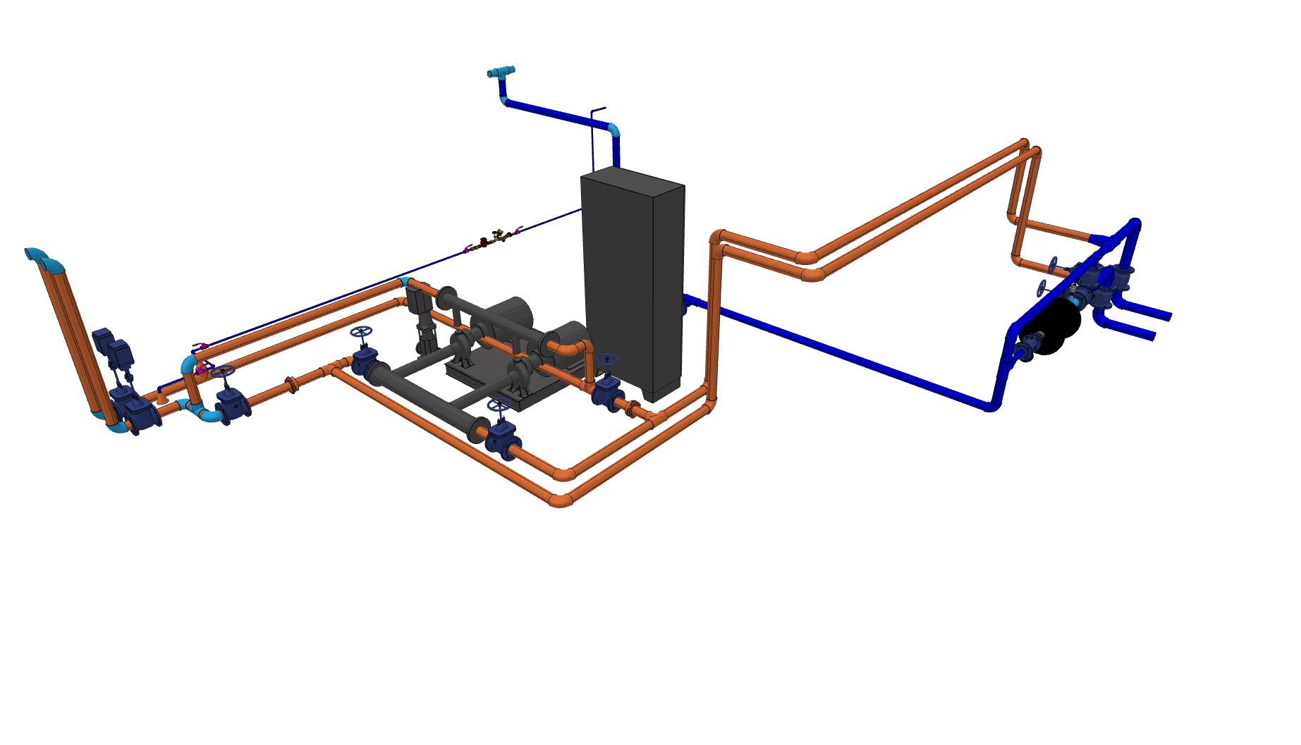
- The full district heating substation (ITP) – modeled in detail with all valves, fittings, and control elements, within a finished room with floor, wall, and ceiling layers
- Three separate drainage systems differentiated by color: main gravity sewer, pump-discharge drainage from the basement sump, and roof runoff collection
- Complete water supply distribution with pumps and all accessories
- Heating system distribution headers and risers
- Full electrical infrastructure: luminaires, outlets, distribution boards, cable trays, fire detection devices, CCTV, and grounding/lightning protection
- Fire suppression system with dedicated pump room
- Ventilation system distribution
Why this matters for construction?
When a general contractor uses this model for construction sequencing (4D) and cost estimation (5D), the basement model is the most critical section. Errors in MEP routing here propagate upward through every floor. On this project, the model was used to identify routing conflicts between MEP pipes and structural elements, and those conflicts were returned to the client with documented evidence before any physical work began.
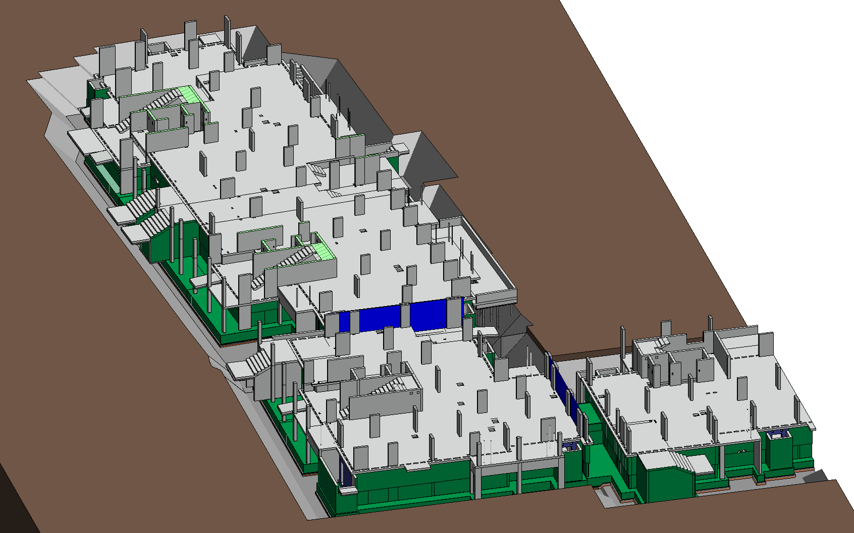
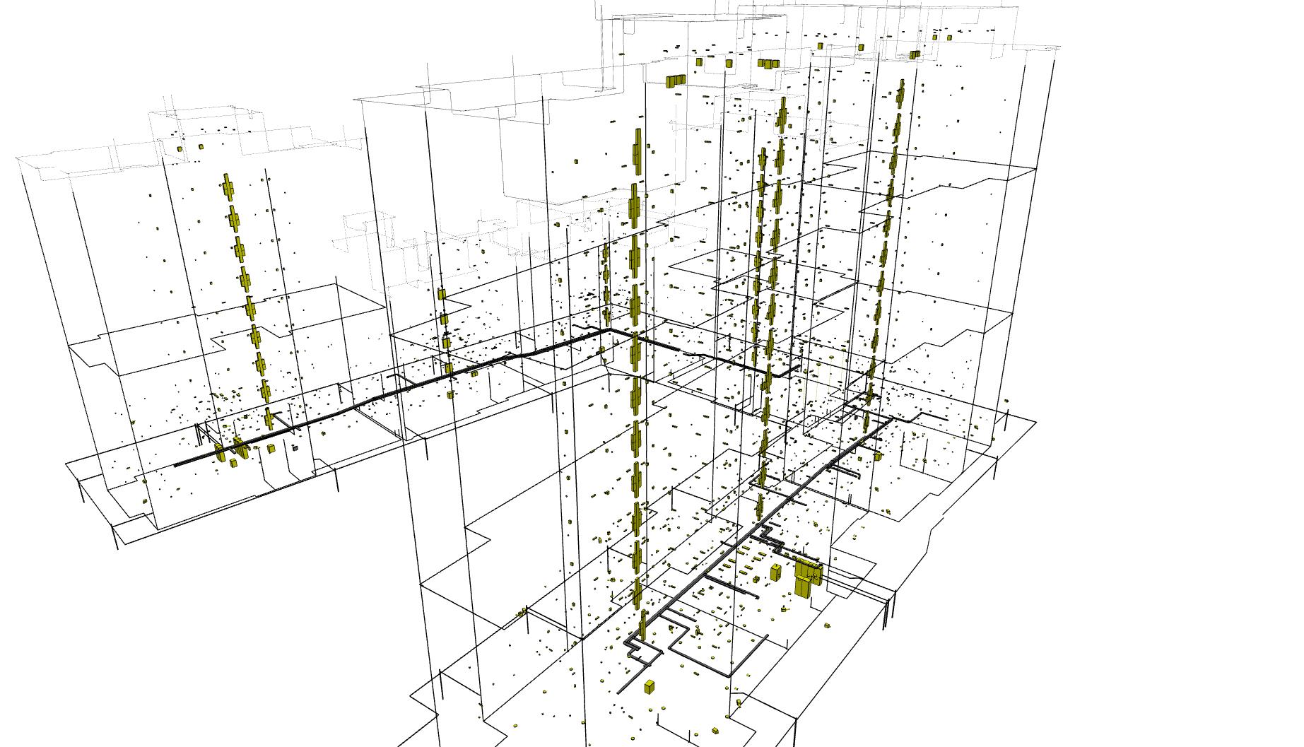
Structural Modeling: From Piles to Roof Parapet
The structural model followed the complete vertical sequence of the building, from the sub-foundation preparation layers through to the roof parapet capping.
- Pile-Supported Terraces
One section of the building featured terraces bearing on concrete piles. In the model, the pile elements, pile caps, and terrace slabs are represented as a connected system, allowing the client to extract accurate concrete volumes and verify the structural logic independently. Thermal insulation within the terrace slab was modeled as a distinct layer, visible in section and accessible for QTO.
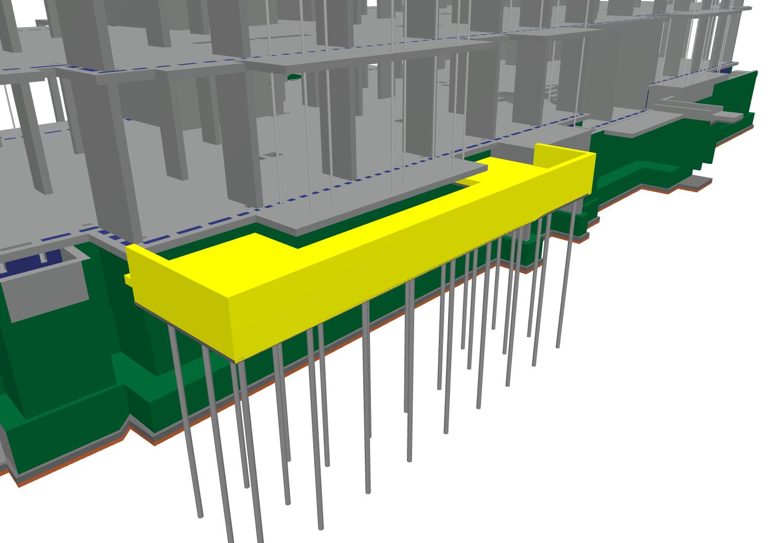
- Sub-Foundation Layers
Below the main foundation slab, the model includes waterproofing membranes and leveling/blinding layers (screed layers below the slab). These are often omitted in BIM models at this LOD but were included here because the client required them for quantity takeoff purposes. Every modeled element can be queried for volume and area, directly from the Revit model, without manual recalculation.

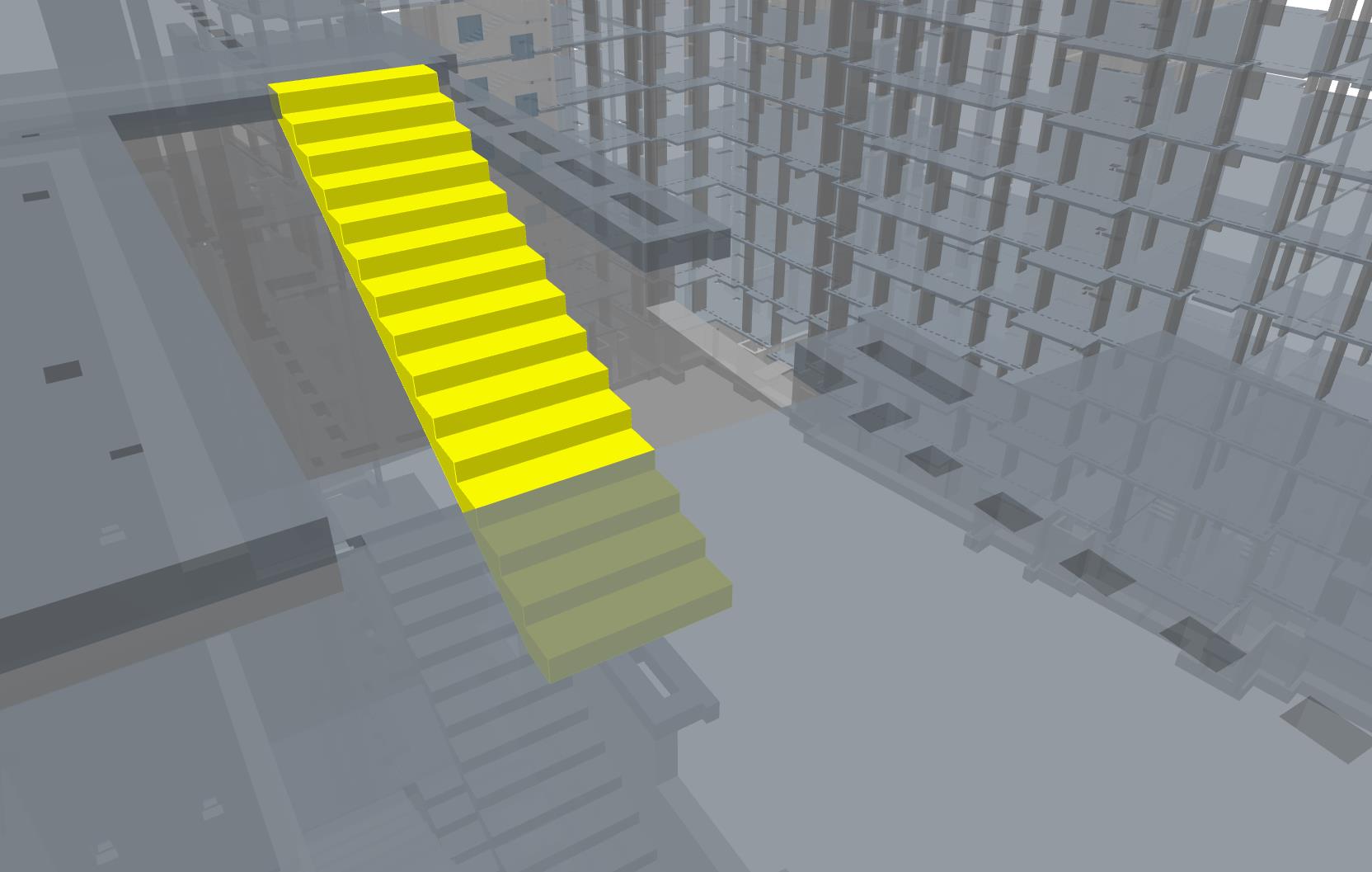
- Stair Flights and Entrance Terraces
External entrance staircases, bridging the height difference between ground floor level and finished ground level, were fully modeled, including the structural flights and the two ground-floor entrance terraces they serve.
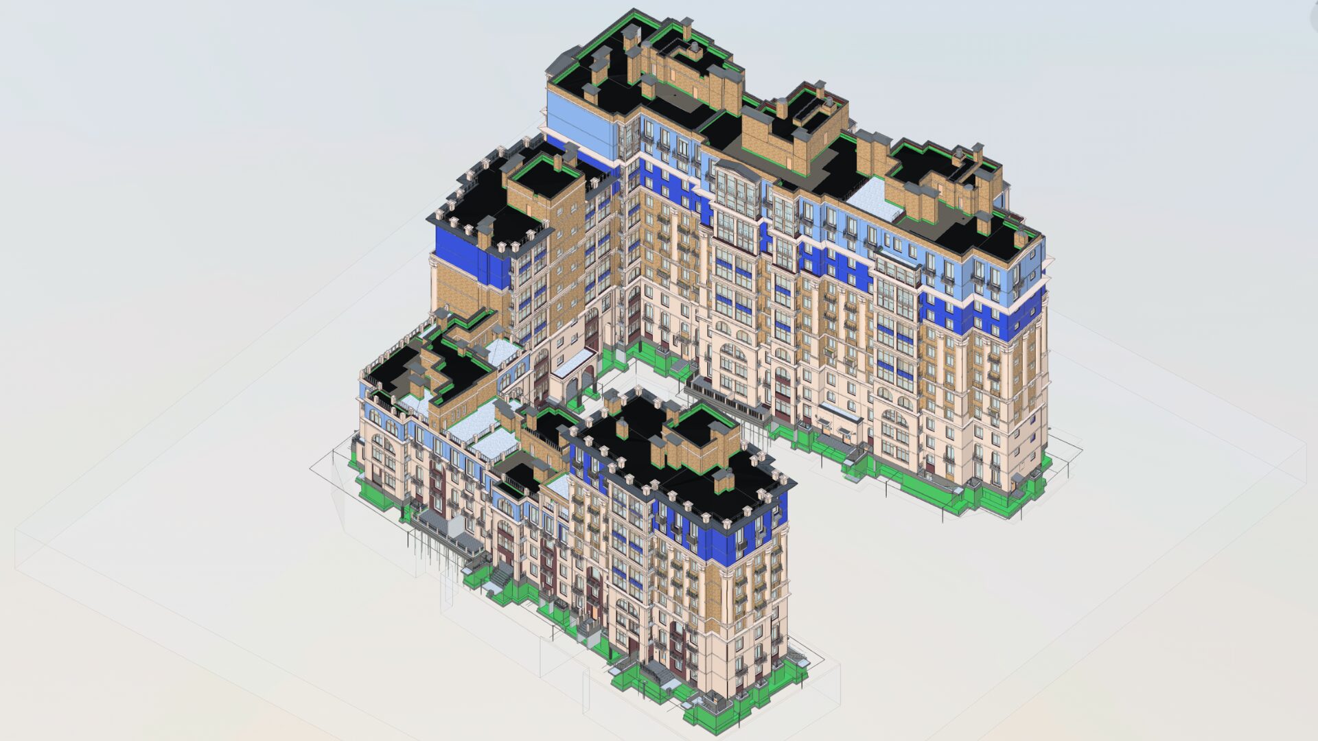
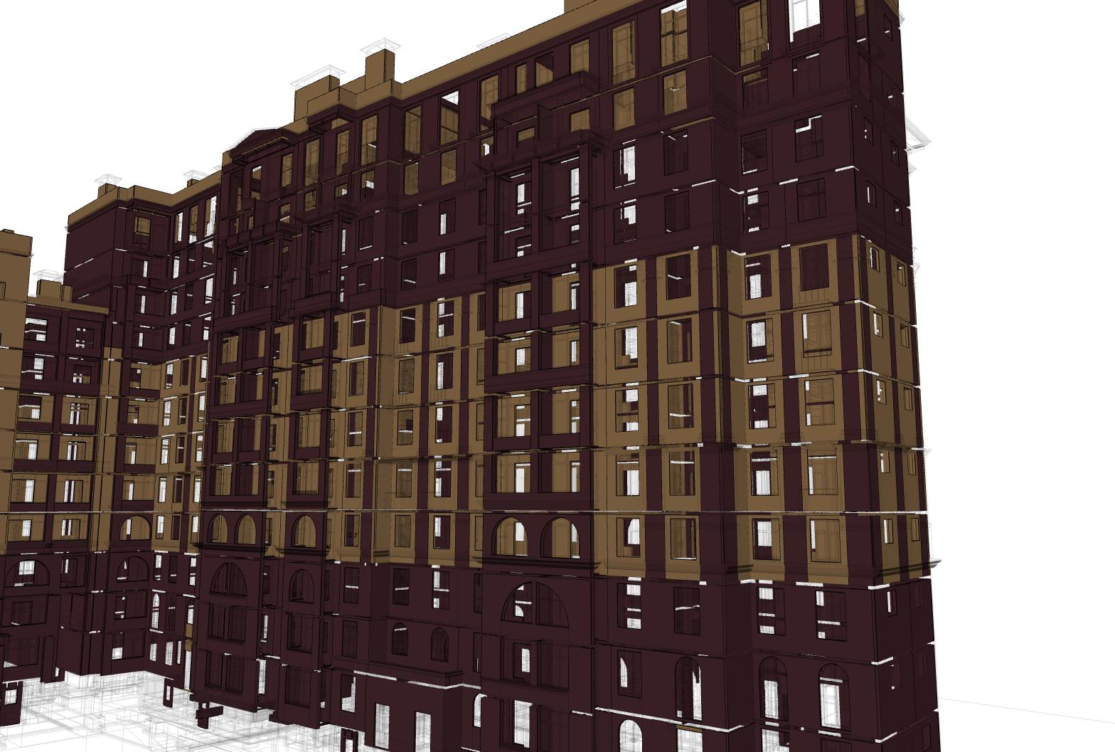
Facade and Masonry: Two Material Systems, Precisely Differentiated
The building envelope combined two distinct masonry systems: autoclaved aerated concrete (AAC) block and brick. Both were used for external (facade) walls; AAC block was also used for interior construction.
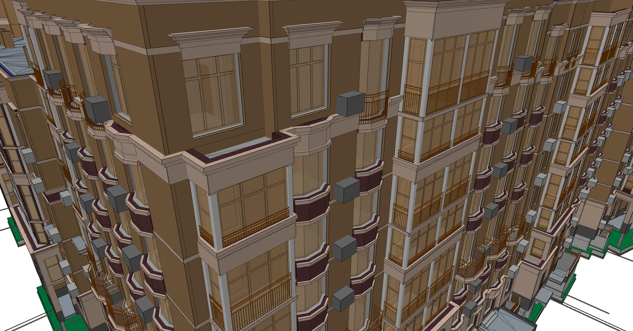
In the model, these are not visually approximate representations. Each material type is modeled as a separate wall type with its own parameters, allowing the quantity surveyor to extract AAC volumes and brick volumes independently, and allowing the structural engineer to verify wall thicknesses.
Exterior AAC walls on this project were typically 400 mm thick.
Facing brick (light color) and non-facing brick (dark) are differentiated by material type in the model, reflecting actual specification requirements on site.
What the Model Was Used For: QTO, 4D, and 5D
The client’s stated use cases for the model were quantity takeoff (QTO), construction sequencing (4D BIM), and cost management (5D BIM). Each of these places different demands on model quality.
QTO
The model needs to be geometrically accurate and parametrically complete. Every element must have the right dimensions and the right material assignment. On this project, every major element – slabs, walls, columns, MEP pipes, cable trays, was modeled with queryable parameters.
A structural concrete slab, for example, exposes its volume and surface area directly from its properties panel.
4D sequencing
Elements need to be logically organized by construction phase and building level. The model’s workset and level structure supports this, enabling the client’s project management team to link model elements to a construction schedule and visualize progress over time.
5D cost management
QTO accuracy is the prerequisite. When quantities are wrong, cost estimates are wrong. The single biggest risk in 5D BIM is model elements that look correct visually but contain incorrect geometric parameters. On this project, that risk was mitigated through systematic documentation review at the input stage.
The Documentation Problem, and Why It’s Almost Always There
It would be easy to frame the documentation issues on this project as unusual. They were not.
On large residential projects, particularly those where design development has occurred over an extended timeline, with multiple consultants working in parallel, inconsistencies between drawing sets are the rule.
The specific types of discrepancies encountered on this project included:
- Dimensional inconsistencies between plan views and section cuts
- MEP systems present in one discipline’s drawings but absent or conflicting in another
- Structural elements referenced in architectural drawings that had no corresponding structural detail
- Room layouts that changed between drawing revisions without corresponding updates to MEP layouts
The value of clash detection
One example from this project illustrates the point clearly. During MEP coordination, it was identified that pipe routes intersected with structural elements, a direct clash that would have required costly on-site remediation if discovered during construction. The issue was documented and returned to the client before the model was finalized. This is one of the clearest demonstrations of why a coordinated 3D model pays for itself.
Every reported discrepancy represents a decision that gets made in the office rather than on the construction site. Office decisions cost time. Site decisions cost time and money – and often, structural integrity.
Key Takeaways for Engineers and Project Managers
For professionals evaluating BIM modeling for a similar project, this case study illustrates several practical points:
- LOD 300/350 is not a cosmetic exercise. At this level of development, the model is a coordination tool, a quantity source, and a documentation record simultaneously. The investment in getting it right at the modeling stage pays dividends at every downstream use.
- Input documentation quality determines output model quality. The modeling team is not a documentation repair service, but identifying and flagging discrepancies during modeling is standard practice on complex projects, and it is far cheaper to resolve them in Revit than on site.
- Multi-discipline coordination in a single model environment is the core value proposition of BIM. When Architecture, Structure, and MEP exist as separate 2D drawing sets, coordination is a manual, error-prone process. When they exist as a federated or combined 3D model, clashes are geometric facts – visible, measurable, and resolvable before construction begins.
- Parametric data is not optional for QTO, 4D, or 5D use cases. A visually accurate model with missing or incorrect parameters is not usable for cost estimation or sequencing. Every element must be queryable.
FAQ
- What is BIM modeling in construction?
BIM modeling is a 3D digital process that integrates architecture, structure, and MEP systems to improve coordination, accuracy, and decision-making in construction projects. - How do Revit modeling services improve project outcomes?
Revit modeling services enable precise 3D modeling, clash detection, and data-rich elements, reducing errors and improving collaboration across all disciplines. - What is 4D BIM construction?
4D BIM construction links the 3D model with the project schedule, allowing teams to visualize construction phases and optimize sequencing and resource planning. - Why is BIM important for large residential, infrastructure, and complex projects?
BIM enables early clash detection, accurate quantity takeoffs, and better coordination across multiple disciplines, reducing risks and costs in complex and large-scale projects. - What were the key benefits of BIM on the Laykovo project?
Improved coordination, early clash detection, reliable quantity data, and better construction planning despite incomplete and inconsistent input documentation.
About NS Drafter
NS Drafter specializes in BIM modeling, rebar detailing, steel detailing and construction documentation for residential, commercial, and complex infrastructure projects. Our teams work across Revit, AutoCAD (ArmCAD), Tekla and Allplan, delivering models and plans depending on project requirements.
