

Revit vs Tekla Structures: Which BIM Platform Really Saves Time in Projects?
As BIM adoption expands from design into construction, the comparison between Autodesk Revit and Tekla Structures (Revit vs Tekla) increasingly centers on how each platform handles reinforcement, structural steel, and the transition from model to site execution. Both tools support structural workflows, but they approach them from different directions, one rooted more in multidisciplinary design, the other in structural detailing and construction processes.
This comparison focuses first on reinforcement modeling, then structural steel, and finally BIM-to-Field capabilities, reflecting how structural projects typically progress from design intent to execution.
Reinforcement Modeling
Reinforcement modeling is one of the areas where the differences between the two platforms become most visible, particularly when transitioning from schematic layouts toward detailed placement and documentation.
Revit vs Tekla
Revit includes reinforcement tools within its structural environment and supports:
Parametric rebar placement
Reinforcement sets and constraints
Coordination with architectural and MEP models
Schedule and documentation generation
Integration with cloud-based BIM collaboration
These capabilities make Revit effective during design development, multidisciplinary coordination, and clash detection phases.
However, in practical reinforcement production environments, Revit often requires:
Additional configuration for complex detailing
Manual adjustments in congested areas
Dynamo scripts or third-party add-ins for automation
Further interpretation before fabrication or site use
In many cases, the reinforcement model represents the design solution, supporting documentation and coordination.

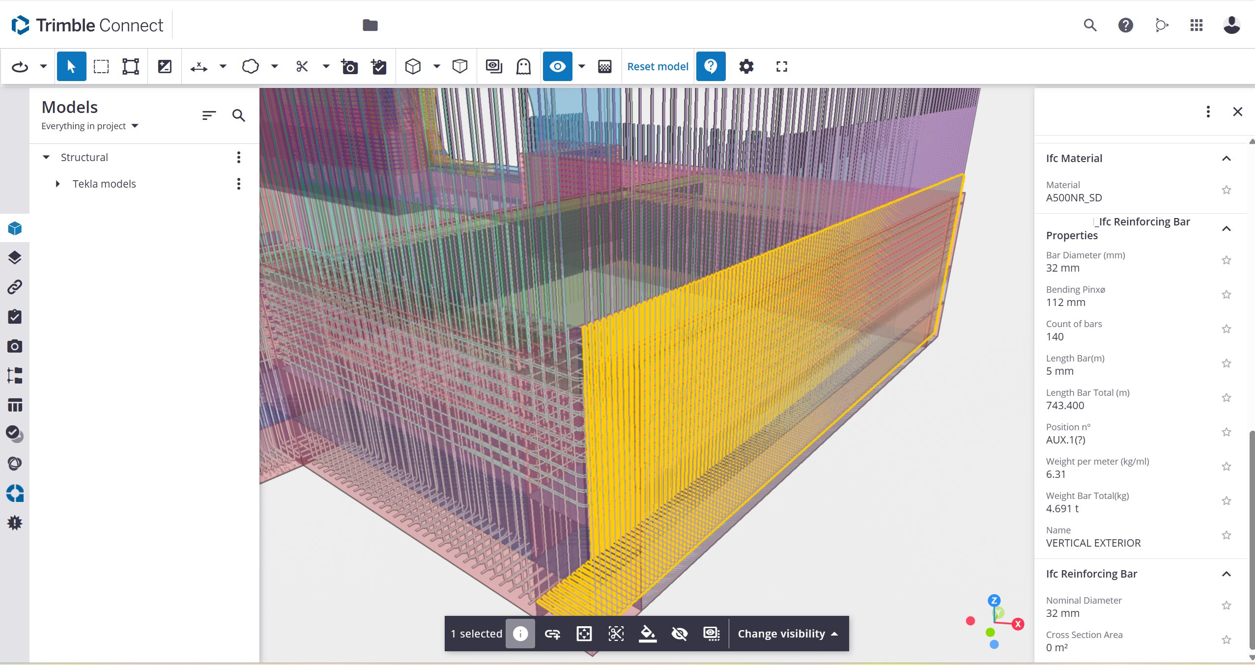
Tekla provides reinforcement tools oriented toward structural detailing and constructability, including:
Detailed bar geometry with bending definitions
Modeling in dense reinforcement zones
Reinforcement assemblies and grouping logic
Automated bar bending schedules
Drawing workflows directly linked to reinforcement objects

In practice, Tekla reinforcement models often serve as the basis for:
Fabrication-ready documentation
Quantity take-offs
Installation sequencing
Coordination with formwork and structural elements
The reinforcement model becomes a production model, not just a design representation.
Structural Steel Detailing
After reinforcement, structural steel is another domain where the two platforms show different priorities and workflows.
Revit for Structural Steel
Revit supports structural steel modeling within the broader BIM environment, including:
Steel members and assemblies
Basic connection modeling
Integration with structural analysis workflows
Multidisciplinary coordination
This makes Revit effective for structural design representation and global building coordination.
However, fabrication-level detailing typically involves:
Additional tools or plug-ins
Further development before production
Separate processes for shop documentation
Steel in Revit is often modeled as part of the overall building design and coordination process rather than as a fully fabrication-ready model.
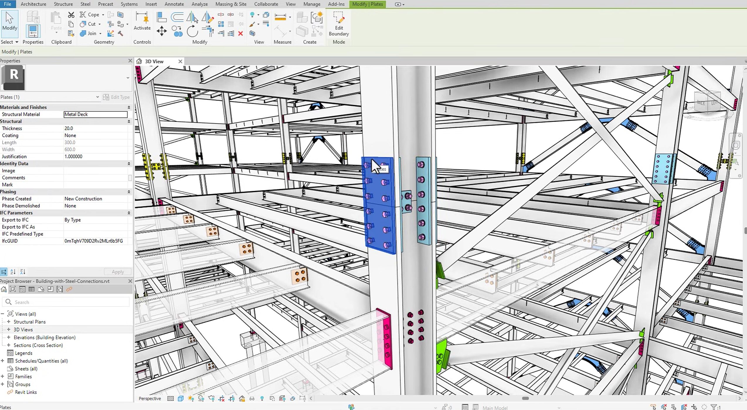
Tekla Structures for Structural Steel
Tekla includes dedicated tools for structural steel detailing, such as:
Parametric connections
Plates, bolts, welds, and assemblies
Fabrication-level geometry
Automated shop drawing generation
Production data outputs

Steel models in Tekla commonly support:
Shop documentation
Fabrication planning
Erection sequencing
Coordination with reinforcement and concrete elements
Steel modeling is therefore closely linked to detailing, production, and construction processes.
BIM Integration and Project Workflows
Revit
Revit is typically used as a central coordination model for architecture, MEP, structural design, documentation, and multidisciplinary collaboration. It integrates with various analysis tools, cloud collaboration platforms, and construction planning systems.
Tekla
Tekla is often introduced when structural models require:
Detailed reinforcement and steel logic
Production-oriented information
Structured fabrication data
High levels of constructability definition
Its integration pathways are strongly aligned with contractors, detailers, and fabricators.
BIM-to-Field Workflows
The transition from digital model to physical construction introduces another important point of comparison.
Revit Contribution to BIM-to-Field
Revit contributes to BIM-to-Field workflows mainly through:
Coordinated 3D models
Documentation and schedules
Exports to construction platforms
Layout and planning support
Before being used on site, model data is often interpreted, processed, or further detailed in downstream software.
Tekla Structures in Bim-to-Field
Tekla models are frequently used in workflows connected to:
Reinforcement placement planning
Steel erection sequencing
CNC bending and fabrication processes
Quantity tracking linked to construction stages
Layout and positioning derived directly from model geometry
In such cases, the structural model participates directly in construction planning and execution processes.
Our Practical Experience with Revit and Tekla
This perspective is grounded in hands-on production experience, not theoretical analysis.
Our company brings together 55 engineers, technicians, and BIM modelers based in Serbia. Our core expertise is rebar detailing, but we also provide steel detailing, structural calculations, BIM modeling and coordination across architecture, structure, and MEP disciplines.
We primarily use Revit, Tekla Structures, Allplan, and AutoCAD including ArmCAD environments, adapting our BIM modeling and reinforcement detailing workflows to client standards, project requirements, and downstream construction processes.
In practice:
If the project is design-driven and coordination-focused, Revit is often dominant, and If the project is production-driven and detailing-intensive, Tekla becomes essential.
Many large projects require both platforms working together.
A typical workflow may involve:
Design and coordination model development
Structural detailing and reinforcement definition
Steel detailing and assembly planning
Model use in construction preparation and execution
Our role is to adapt to each project ecosystem while maintaining reinforcement accuracy, constructability awareness, and production-ready outputs.
Software is a tool. Structural knowledge, detailing logic, and understanding of concrete behavior, reinforcement rules, and steel fabrication processes remain the foundation of successful project delivery.
Which Platform Really Saves Time?
Revit saves time in coordination.
Tekla saves time in production.
The real time loss happens when a design model must be reinterpreted before fabrication or site execution.
When BIM strategy matches the project phase, rework decreases, detailing becomes more predictable, and site performance improves.
The fastest workflow is not about software preference, but about aligning the right tool with the right stage of the project lifecycle.
Conclusion
The comparison between Tekla and Revit in reinforcement, steel detailing, and BIM-to-Field workflows is less about selecting a single platform and more about understanding their roles within the lifecycle of a structural project.
Revit operates strongly in multidisciplinary BIM environments and early project stages, where coordination and design development are central. Tekla is frequently applied when structural models evolve toward detailing precision, fabrication data, and construction workflows. Together, they illustrate how BIM transitions from a design environment into a construction-driven process, particularly in reinforced concrete and structural steel projects.
FAQ
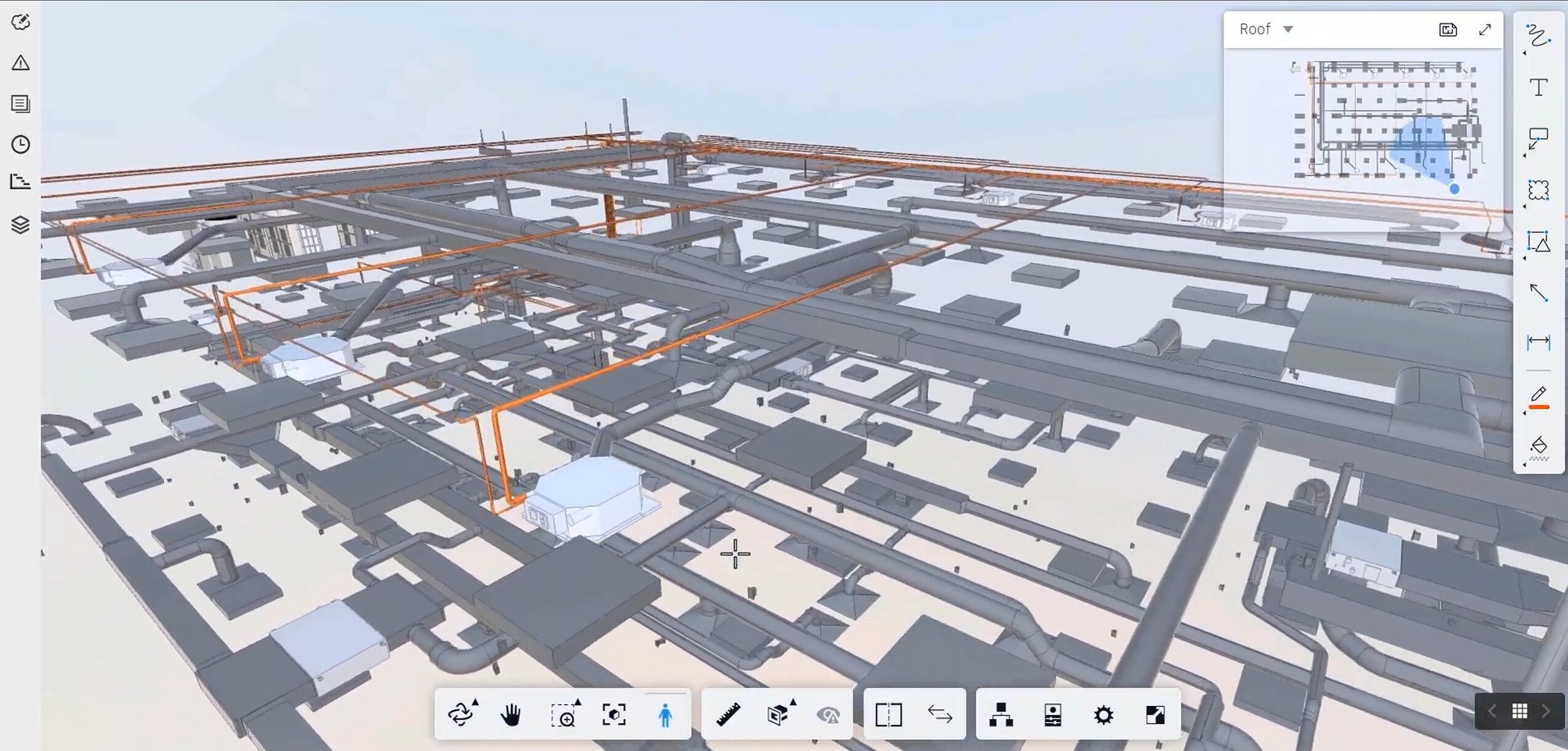
What are the top software tools for BIM-to-Field data integration?
Autodesk Construction Cloud, Trimble Connect, Procore, Bentley ProjectWise, and Revizto are among the most used platforms. They connect 3D models with field documentation, issue tracking, and scheduling. For structural projects, integration with layout systems like Trimble or Leica is often essential.
Which companies offer BIM-to-Field solutions for heavy civil construction?
Trimble, Autodesk, Bentley Systems, Leica Geosystems, and Topcon are leading providers. They combine design software, cloud platforms, and machine control systems for infrastructure and large civil works.
How do the latest BIM software updates improve cloud collaboration?
Recent BIM software updates significantly improve cloud collaboration by integrating key coordination tools directly into the main modeling interface, allowing teams to work in real time without relying on separate web applications.
Features such as live model sharing and synchronized updates enable multiple users to work on shared models with clear visibility of changes, including detailed change tracking at element and property level. Clash detection is increasingly embedded within the core software, allowing modelers to run checks, assign responsibilities, and monitor resolution status directly in the modeling environment.
In addition, BCF-based issue management is now typically integrated, making it possible to create topics from model views, assign tasks, add comments, attach viewpoints, and track issue progress without leaving the platform. At the same time, all this information remains accessible through simplified web interfaces for other project participants, ensuring that modelers maintain full technical control while stakeholders can review models, follow discussions, and monitor revisions online in real time.
Why is model data quality critical for BIM-to-Field workflows?
Model data quality is critical for BIM-to-Field workflows because the model is no longer just a coordination tool; it becomes the primary source of information for planning, fabrication, and site execution.
For BIM to be usable in the field, the data must be structured, consistent, and construction-ready, with clearly defined reinforcement logic, steel detailing, attributes, sequencing, and element relationships. If this information is incomplete, inconsistent, or modeled only geometrically, site teams are forced to reinterpret the model, verify assumptions, or recreate information through drawings and manual checks, which reduces efficiency and increases the risk of errors.
High-quality model data enables reliable exports, accurate quantity takeoffs, automated drawings, and direct use in fabrication and site workflows, while poor data quality breaks this chain and turns BIM back into a visual reference rather than an operational tool.
What are the most common obstacles in BIM-to-Field implementation?
The most common obstacles in BIM-to-Field implementation are still related to process alignment rather than technology itself. One of the main challenges is unclear responsibility between designers, detailers, and contractors, as well as modeling that is done primarily for coordination instead of for construction execution.
Even when high-quality models exist, construction sites are still in a transitional phase and often rely on a hybrid approach to information delivery.
Site engineers frequently depend on traditional drawings and plan-based documentation, and a model on its own, without structured filtering and interpretation, can be difficult to use directly in daily site operations. Because of this, BIM teams often need to take a more advanced role in analyzing model data, preparing exports carefully, filtering and structuring key information, and sometimes producing simplified drawings or additional documentation that translate model intelligence into practical instructions for the field.
The challenge is therefore not only technical but organizational: aligning modeling standards, export logic, and site expectations so that BIM outputs become actionable and usable rather than just technically correct.
