

Tekla Marking Tool: A Complete Guide to Exporting Layout Points Without Errors
Overview
Concrete contractors spend a surprising amount of time arguing about a single dot. That dot – a layout point, anchor mark, or setting-out coordinate – has to travel from a Tekla Structures model to a total station on site without losing a millimetre or a digit of its ID. The Tekla marking tool is the bridge that gets it there.
This guide walks you through what the Tekla marking tool actually does, how to set it up, how to export points cleanly to the field, what real clients ask for (rarely what textbooks describe), and the errors we see most often at NS Drafter when we audit other detailers’ models.
What Is the Tekla Marking Tool?
The Tekla marking tool is the family of features inside Tekla Structures used to define, name, manage, and export layout points – physical coordinates that get transferred to the construction site for setting-out, anchor placement, embed positioning, and quality-control verification.
Marking ≠ Numbering
A common confusion: in Tekla, “numbering” refers to assigning position marks to parts and assemblies (B1, B2, P1, …). “Marking”, as concrete contractors use the term, refers to setting-out, the act of physically marking a point on the slab or formwork before pouring or installing. The Tekla marking tool belongs to the second category. If your question is about position numbers on shop drawings, that is a separate workflow and not what the Tekla marking tool covers.
Where Layout Points Fit in the Concrete Contractor Workflow
For a concrete contractor, the chain is straightforward: model → layout points → field device → physical mark on site.
The model is authoritative, the field device (typically a Trimble robotic total station) is the executor, and the layout points generated by the Tekla marking tool are the contract between them.
A misplaced point in the model becomes a misplaced anchor on site, and a misplaced anchor becomes a change order.
Tekla Layout Marking Workflow (Four Tools, One Job)
Tekla layout marking is not a single command. It is a coordinated set of four tools inside the Tekla marking tool family, each handling a slice of the lifecycle.
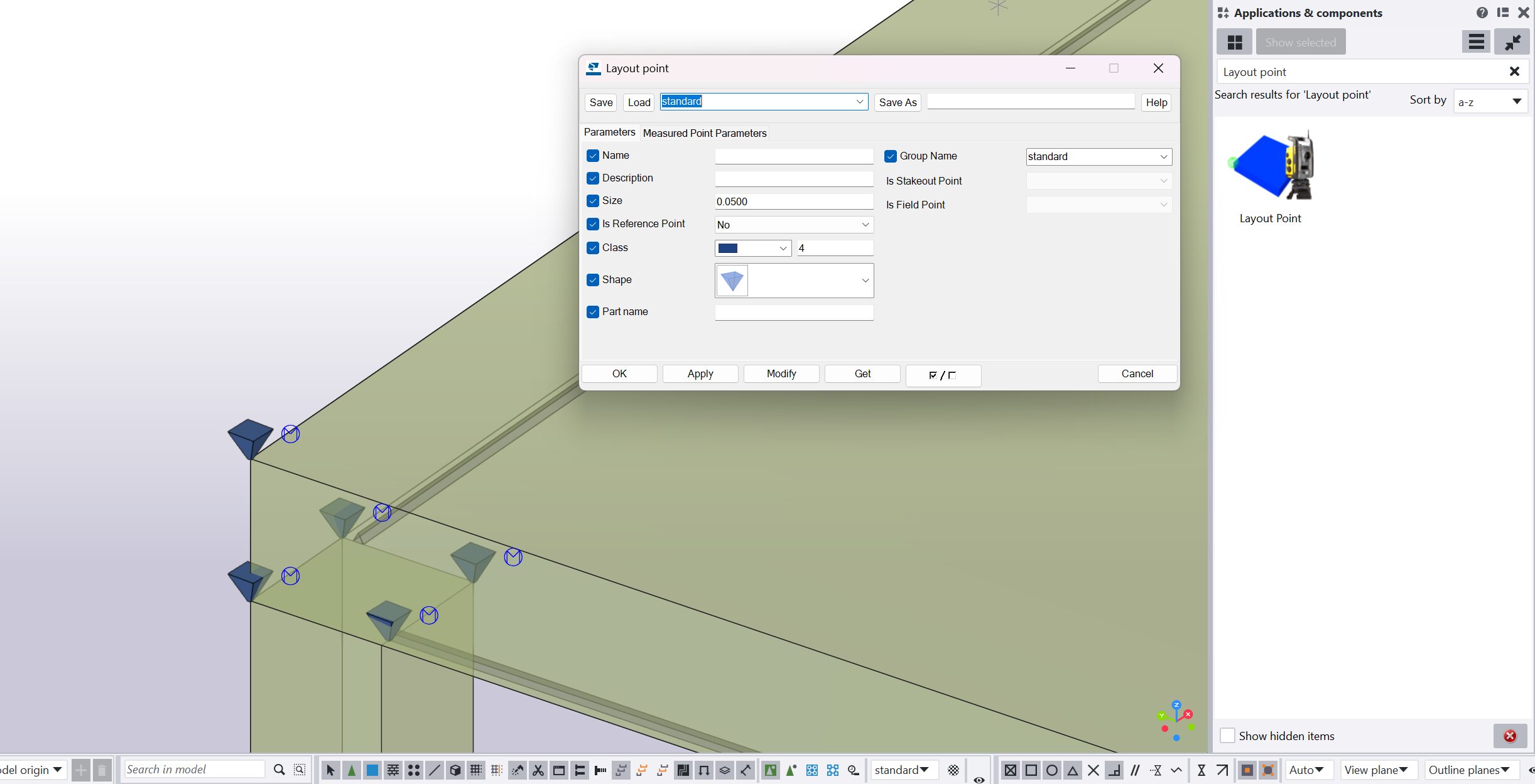
Layout Point, the Geometry Primitive
The Layout Point is the basic object: a 3D coordinate with an ID, a description, and an optional link to a parent part. You can place layout points manually by picking coordinates, snap them to part geometry, or generate them from a reference object. Each point carries metadata that will follow it all the way to the total station.
Layout Point Applicator, Repeating Patterns on Parts
When the same pattern needs to be repeated across many parts, for example, a 4-anchor pattern on every column base plate, the Layout Point Applicator lets you define the pattern once and apply it parametrically.
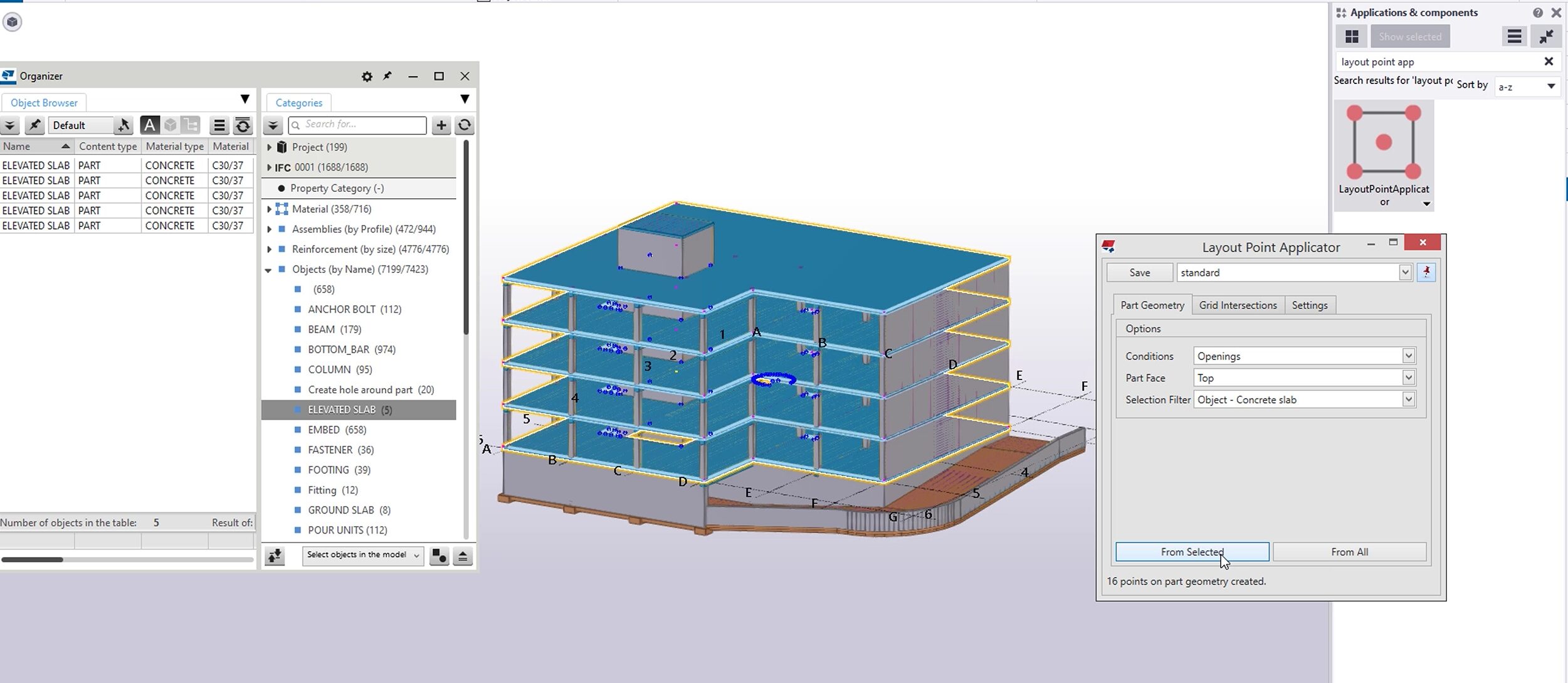
If the parent part moves, the applicator points move with it. This is the difference between a model that survives revisions and a model that requires re-marking after every design change.
Layout Manager (Grouping, Naming, Status)
Layout Manager is the dashboard of the Tekla marking tool. It groups layout points into logical sets (by floor, by phase, by contractor scope), assigns status (planned, marked, verified), and controls what gets exported and when. A clean Layout Manager structure is the difference between sending the field crew 200 points or 2,000.
Organizer (Cross-Model Categorization)
The Organizer adds another dimension to Tekla layout marking: it lets you slice the same layout points by property, by IFC class, by phase, by custom attribute. For multi-discipline projects this is essential, because the rebar contractor, the formwork contractor, and the MEP installer will each want a different subset of the same point cloud.
Step-by-Step: Tekla Marking Export to the Field
Here is the production sequence we use on NS Drafter projects when running a Tekla marking export for a Trimble total station.
Step 1 I Define the Local Coordinate System First
Before placing any point, agree with the site team on the coordinate system. Tekla can export against the global model origin, a project base point, or a user-defined local system.
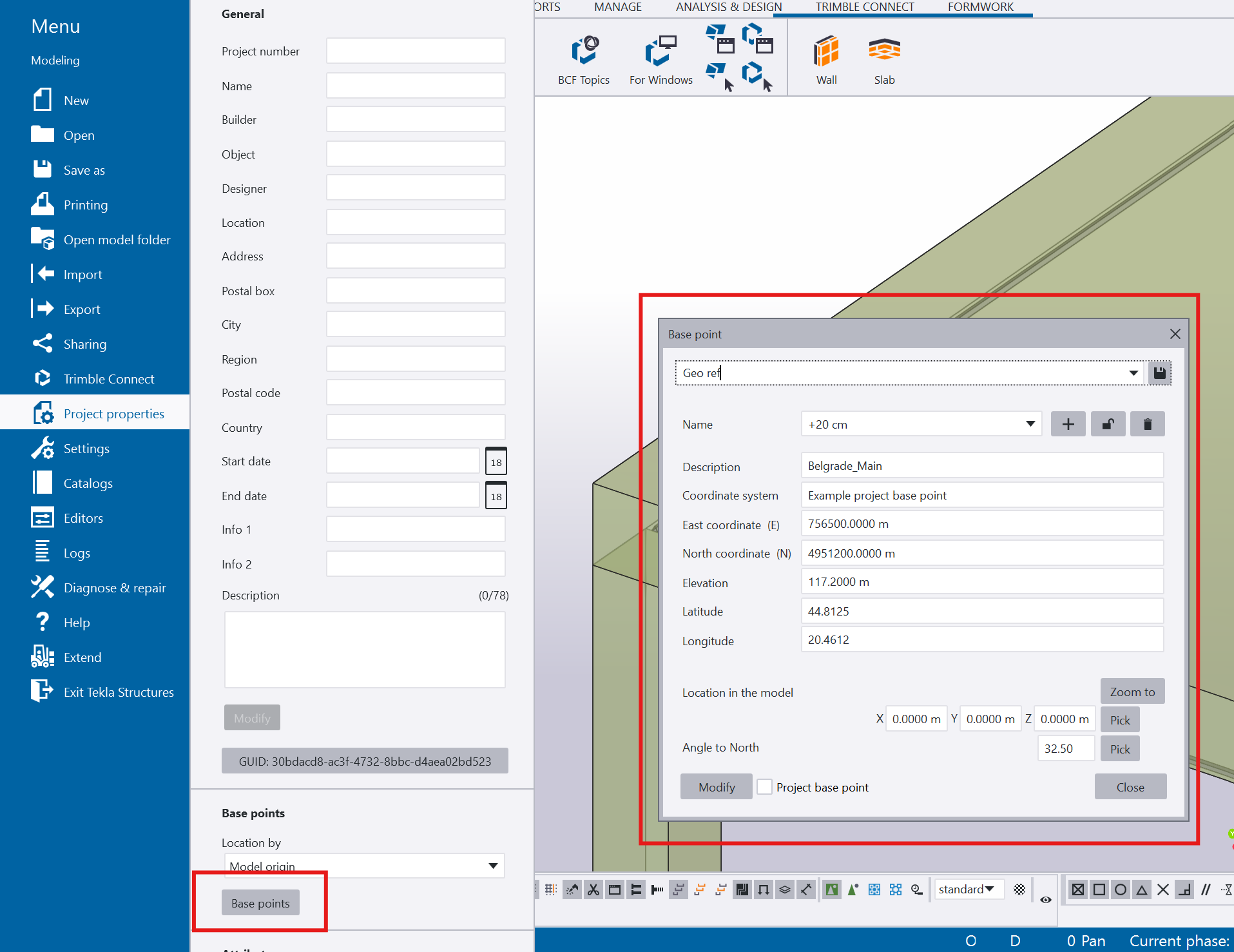
Choose one, document it, and lock it in the model template.
90% of the field errors we have audited trace back to this step.
Step 2 I Create the Points (Single, Outline, or Pattern)
Place points using the Layout Point tool for one-off coordinates and the Layout Point Applicator for repeating patterns. Snap to part geometry whenever possible so that future revisions propagate automatically. Avoid free coordinates, they are orphans in revision tracking.
Step 3 I Group in Layout Manager
Open Layout Manager and assemble the points into named groups that match how the site team works: by pour sequence, by contractor scope, or by date. Each group should answer one question: “what is the field crew marking on which day?”
Step 4 I Run the Tekla Marking Export to Total Station, CSV, or IFC
The Tekla marking export options most commonly used are direct export to Trimble field software (Trimble Connect, Trimble Field Link), CSV export for generic total stations, and IFC export for downstream BIM coordination.
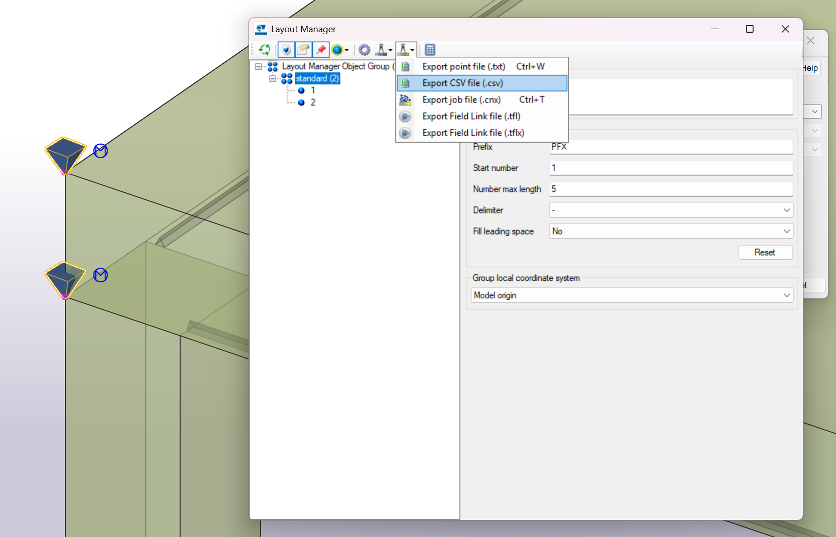
Always include the point ID, X/Y/Z, and description columns. Strip everything else, field controllers are not the place for verbose metadata.
Step 5 I Validate Before Sending
Run a coordinate sanity check on at least three sample points by comparing model values against an independent measurement (a section view dimension, for example). Then verify the file in the target field-software preview before it leaves the office. A five-minute validation step prevents a five-hour site delay.
What Clients Actually Ask For: Field Reality vs. Textbook
This is the part that documentation does not cover. After dozens of concrete contractor projects, our NS Drafter team has observed that real-world requests for marking from Tekla rarely match the comprehensive workflows shown in tutorials.
One Point at a Pre-Chosen Coordinate (Most Common)
The single most frequent request is a single layout point at a coordinate the client has already picked themselves. They do not want us to engineer the setting-out, they want the model to confirm a coordinate they have committed to. The work is mostly verification: does the point land where the model says it should, and does its ID match the field drawing.
Gabarit / Outline Points of the Object
The second most common request is outline points, the corner coordinates of an object’s bounding footprint. Four points on a foundation, six on an irregular slab, eight on a column cluster. This pattern lets the crew chalk the perimeter before anything else is marked, and it is fast to produce in Tekla via the Layout Point Applicator.
Full Grid of Anchor and Embed Points
A minority of clients, usually steel-on-concrete projects or precast erectors, request the full anchor and embed grid: every bolt, every plate, every threaded insert as an individual point with an ID. This is the most labor-intensive pattern and the one where Layout Manager hygiene matters most, because the output can easily exceed a thousand points per pour.
Why There Is No Universal Rule
There is no universal standard for how many layout points a model should contain. The answer depends on the contractor’s equipment, the crew’s experience, the project schedule, and the local convention.
The right approach is to ask the contractor first and model second, never the other way around.
Detailers who try to impose a “best practice” point density without asking usually end up redoing the work.
Common Errors in Marking from Tekla, and How to Fix Them
The errors below are the recurring patterns we see when auditing third-party models for marking from Tekla.
Wrong Coordinate System (Project Base vs. Global)
The most expensive error. Points exported against the global origin instead of the project base land hundreds of meters away on site.
Fix: lock the export coordinate system as a project template setting and verify it during pre-flight every single export.
Points Lost After Phase or Numbering Change
When the model is re-phased or re-numbered, free layout points (not snapped to parts) can be dropped, duplicated, or re-IDed.
Fix: always snap points to a parent part using the Layout Point Applicator, never to a free coordinate.
Duplicate Points Across Assemblies
Two identical coordinates with two different IDs confuse the field crew and produce two marks on site.
Fix: run Layout Manager’s duplicate report before every export. Cleanup takes minutes; field rework takes days.
Export Precision Rounding
Default CSV export sometimes truncates coordinates to two decimals, a 5 mm offset becomes a 1 cm gap on site.
Fix: configure the Tekla marking export template for four decimals (sub-millimeter) and confirm precision in the target field software.
Best Practices for Shop-Ready Layout Marking I NS Drafter Checklist
These are the rules we run through before any Tekla marking export leaves our office. The same checklist applies to rebar detailing handoffs and to formwork drawings.
Ask the Contractor First, Model Second
The first email on any project asks four questions: which coordinate system, which field device, which point density (one, outline, or full grid), and which export format. The model follows the answers, not the other way around.
Lock the Coordinate System Early
Set the project base point and lock it in the model template before any point is placed. Communicate it in writing. Re-baselining the coordinate system mid-project is the most reliable way to lose a day of work.
Version Point Sets per Construction Phase
Treat each Layout Manager group as a deliverable with a version number. When the field crew receives an export, the file name should tell them which phase, which revision, and which date. Anonymous “points.csv” files are how site mistakes start.
FAQ
Q: What is the Tekla marking tool used for?
A: The Tekla marking tool is used to create, manage, and export layout points from a Tekla Structures model to field devices for setting-out and quality control on concrete construction sites. It includes the Layout Point, Layout Point Applicator, Layout Manager, and Organizer features.
Q: How do you export layout points from Tekla to a total station?
A: Place layout points in the model, group them in Layout Manager, then run the Tekla marking export either directly to Trimble Connect or Trimble Field Link, or as CSV/IFC for generic total stations. Always validate point IDs, coordinates, and precision before the file leaves the office.
Q: What is the difference between Layout Point and Layout Point Applicator?
A: A Layout Point is a single coordinate object. The Layout Point Applicator places a pattern of layout points parametrically on a parent part, so the pattern updates automatically when the part is modified.
Q: Can I export Tekla marking data to CSV or Excel?
A: Yes. The Tekla marking export supports CSV output containing point ID, X/Y/Z coordinates, and description columns, which can be opened directly in Excel or imported into total station software.
Q: Why do my Tekla layout points disappear after model updates?
A: Most often because the points were placed as free coordinates rather than snapped to a parent part. Use the Layout Point Applicator on a parent part so that points survive numbering changes, phase reassignments, and geometry edits.
For a deeper dive into our broader Tekla workflow, see our overview of the and our . For the broader field-handoff context that layout points sit inside, our and the analysis of cover the integration patterns end-to-end. To see how the Tekla marking tool ties into our complete delivery process, read about .
For Tekla’s own reference material, see the . For total station integration, the explains the end-to-end data flow.
About Us
NS Drafter specializes in BIM modeling, rebar detailing, steel detailing and construction documentation for residential, commercial, and complex infrastructure projects. Our teams work across Revit, AutoCAD (ArmCAD), Tekla and Allplan, delivering models and plans depending on project requirements.
Curious how we would approach your next project? Get in touch.
