
Successful Construction Case Study I 55.000 m² in Amsterdam
Overview
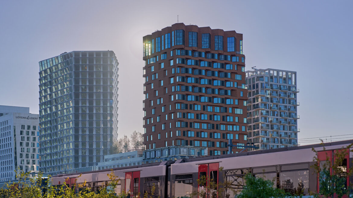
The Pulse of Amsterdam, represents one of the most significant contemporary examples of integrating architecture, construction, sustainability, and digital technologies within urban development in European metropolitan areas. Located in the Zuidas business district of Amsterdam, this project is not just another high-rise building, but a paradigm of future urban systems.

It is a complex that functions as a “city within a city,” where living, working, recreation, and nature are combined into a single, highly optimized whole. Projects of this type require a completely new approach to design, where precise rebar detailing, and coordination between disciplines become critical success factors.
Basic information:
- Location: Amsterdam, Zuidas
- Completion: November 2024
Unlike traditional projects, where functions are clearly separated, De Pulse integrates everything into one structure, which directly increases construction complexity and requires a much higher level of planning and execution precision.
Horizontal and Vertical Parameters
The total site area ranges between approximately 8,000 and 10,000 m², with a footprint coverage of 70% to 80%, resulting in a building footprint of around 6,000 to 7,500 m².

The total gross floor area (GFA) is estimated between 55,000 and 60,000 m², distributed as follows:
- office space ~35,000–36,000 m²
- residential space ~18,000–20,000 m²
- commercial facilities ~8,000–10,000 m²
The vertical massing of the building has been carefully optimized to ensure good solar exposure and minimize mutual shading between volumes.
Functional Layout Organization
One of the key aspects of the project is the differentiated floor plan organization depending on the function.
- Office Tower
Typical floor plates range from 1,200 to 1,600 m², with a floor depth of 12 to 18 meters. This configuration allows for optimal natural lighting and high flexibility in space planning.
- Residential Tower
Floor plates are more compact, ranging from 600 to 900 m², with a central core and perimeter-arranged apartments. This layout ensures good daylight access and natural ventilation for all units.
- Plinth (Base Structure)
The base is characterized by large spans and floor heights between 4.5 and 6 meters, accommodating functions such as cinemas and retail. This directly influences the selection of the structural system.

Basement Levels and Logistics
The building includes 1-2 basement levels containing parking and technical rooms. Due to a high groundwater level, advanced waterproofing systems (“white tank”) were implemented.
Construction logistics posed a significant challenge due to limited space and a dense urban environment, which was addressed through precise planning and phased execution.
Structural and Engineering Systems
The primary structural system is based on a reinforced concrete frame with central cores designed to resist horizontal loads (wind).
Column grids vary depending on function: office areas 7.5-8.4 m, residential areas 5.4-7.2 m.
Zuidas: Redefining the Modern Business District
Zuidas is planned as the central business district of Amsterdam, with the ambition to become equivalent to global financial centers such as Canary Wharf in London or La Défense in Paris.
However, modern urban planning goes beyond this concept.
Traditional business districts often suffer from so-called “dead zones,” spaces that function only during working hours. Outside of that period, they lose their purpose and remain inactive.
De Pulse directly addresses this issue through a mixed-use concept:
- offices
- residential
- commercial amenities
- public spaces
By integrating these functions, the project ensures continuous activity throughout the day, reduces the need for transportation, and significantly improves urban living quality.
From a technical perspective, this approach introduces a much higher level of complexity and coordination between disciplines.
Scope of Work
The scope included full reinforcement detailing of key structural elements:
- columns
- walls
- beams
- slabs
Each element was modeled and detailed with a high level of precision, fully aligned with the design documentation. In projects of this scale, model accuracy directly impacts construction efficiency and overall project performance.


Coordination between architecture, structure, and MEP systems was carried out within in an integrated environment. Instead of working with separate drawing sets, all disciplines were integrated into a single model, allowing early identification and resolution of potential clashes.
This approach enables optimization of reinforcement based on real spatial constraints, more reliable quantity take-offs, and improved prefabrication processes. In this context, rebar detailing was not an isolated activity, but an integral part of the overall workflow.
Workflow Optimization: From Manual Drafting to Automation
One of the key challenges on the project was balancing a high level of detail, tight deadlines, and complex geometry. A traditional approach to rebar detailing, largely based on manual drafting, becomes a limiting factor under such conditions.
To address this, BFW software was implemented during the project, enabling:
- automation of the rebar detailing process
- standardization of drawings
- significant reduction of errors
- increased production speed
This implementation allowed the team to maintain high-quality outputs while keeping up with the demanding construction schedule. It clearly demonstrates that digital tools are no longer optional in modern construction workflows, but essential.
BFW Software
Software that introduces continuity between detailing and production transforms reinforcement from drawings into a direct input for the factory.
For contractors and reinforcement factories, traditional workflows often lead to lost time, inefficient production planning, and unnecessary material waste. Instead of fragmented steps and manual processing, the workflow becomes a unified data flow, from the 3D model, through bending schedules, to cutting and bending machines.
In practice, this approach can deliver over 30% faster preparation, which on this project meant reducing timelines from 420 to 288 working days.
It also minimizes errors, optimizes material usage, and accelerates preparation, enabling complex projects to be managed more reliably with greater control over timelines and costs.
What makes an additional difference is the ability to use the same data across the entire chain, from design and preparation to production and logistics.
BFW does not function as an isolated tool, but as a central integration platform connecting BIM/CAD environments, CNC machines for rebar processing, and production planning systems.
Another key aspect is the software’s ability to perform automatic geometry checks, from bending radii to total bar lengths, resolving issues before they reach the factory or site. In addition, grouping bars by similar characteristics (diameter, shape, length) enables optimized production batches, which in practice can reduce material waste by 10-15% while improving machine utilization.

During these projects, it was also possible to explore new reinforcement design concepts such as Progress Nets technology.
This approach moves away from traditional bar-by-bar detailing and instead organizes reinforcement into predefined, optimized mesh units tailored to specific structural elements. These “nets” integrate main reinforcement, additional bars, and lap zones into a single, coordinated system that can be prefabricated and delivered as ready-to-install units.
By standardizing and modularizing reinforcement in this way, Progress Nets improves fabrication accuracy, reduces material waste, and significantly speeds up on-site installation while maintaining full control over structural performance.
The value of this approach is not just speed, but process stability.
When data is consistent and connected across all stages, projects are delivered with less improvisation and greater predictability, marking a clear shift from traditional workflows to digitally driven construction execution.
Main Challenges
The structural system is based on a reinforced concrete frame with central cores that resist horizontal loads. Additional complexity arises from the variation in column grids between office and residential zones, requiring different modeling and detailing approaches.
The use of the Cobiax slab system provides significant advantages in reducing structural weight and increasing spans, but it also requires precise coordination between voids and reinforcement.

This was one of the most technically demanding aspects of the project.
The foundation system is based on piles, combined with waterproofing solutions due to the high groundwater level, which further complicates both design and construction.
Why precision is critical:
Errors in the model directly affect:
- construction (delays, on-site modifications)
- prefabrication (incorrect quantities and elements)
- scheduling (delays in execution)
For this reason, precise 3D modeling and detailing were essential throughout the entire project lifecycle.
Vertical City in Practice
The “vertical city” concept is the core of the project, replacing traditional horizontal zoning with vertical organization.
The complex consists of:
- office tower (~92 m)
- residential tower (~81 m)
- plinth

This configuration enables clear functional zoning, with public amenities located in lower levels and business and residential spaces positioned above.
 While this approach improves space efficiency and urban dynamics, it also significantly increases the need for coordination between all systems within the building.
Interesting Facts
De Pulse is designed as an energy-neutral building, incorporating advanced systems that contribute to sustainability. A large surface area of solar panels supports renewable energy production, while energy exchange systems between building functions improve overall efficiency.
Advanced HVAC systems with BMS control optimize energy consumption, and water collection and recycling systems enhance resource management. A particularly notable feature is the “city biotope” concept, which introduces multi-layered greenery throughout different height zones of the building.
From a structural perspective, sustainability is also reflected in material optimization. Reducing the volume of concrete and reinforcement through intelligent design and systems like Cobiax directly contributes to lowering the building’s carbon footprint.
Conclusion
FAQ
Q: What is BIM in construction?
A: BIM is a digital process that integrates all project disciplines into a single 3D model to improve coordination and decision-making.
Q: Why is rebar detailing important?
A: It ensures accurate reinforcement placement, reduces errors, and improves construction efficiency.
Q: What is the Cobiax system?
A: It is a voided slab system that reduces structural weight and allows for larger spans.
Q: How does BIM impact project costs?
A: It reduces errors, improves planning, and optimizes resource usage, directly lowering overall costs.
About Us
NS Drafter specializes in BIM modeling, rebar detailing, steel detailing and construction documentation for residential, commercial, and complex infrastructure projects. Our teams work across Revit, AutoCAD (ArmCAD), Tekla and Allplan, delivering models and plans depending on project requirements.
Our Project Case Studies:
