
3 Major Infrastructure Projects We Worked On I Inside the Rebar Detailing and BIM Workflow
Overview
Infrastructure projects operate on a different scale than commercial or residential construction. A single viaduct pier can require more reinforcement steel than an entire mid-rise residential building. A metro station integrates structural, mechanical, and operational systems into one underground volume that has to function for the next 100 years.
The structural design isn’t usually where things go wrong. The calculations, the load analysis, the global geometry, all of that arrives correct on most projects.
What breaks the schedule and the budget is the layer between the design and the pour, where structural drawings have to be translated into something a fabricator can produce and a site crew can install. On infrastructure projects, this layer is where most of the time, money, and risk actually lives.
This blog looks at three infrastructure projects we worked on, the West Gate Tunnel in Melbourne, a precast bridge structure, an underground metro station, and how reinforcement modeling, BIM coordination, and site-aware detailing changed the way each one was delivered.
The point isn’t to showcase software. It’s to show what infrastructure projects actually demand from a detailing team once the model meets the production schedule.
Why Infrastructure Projects Demand a Different Approach
Infrastructure projects come with constraints that don’t exist on most building projects. Precast tonnages run into tens of thousands of tons. Construction phasing is tied to active road or rail operations. Underground work happens in confined volumes where geometry is fixed by tunnel boring or excavation methods, not by the designer’s preference.
These conditions change what the model has to do. On a residential project, the model is a coordination tool, the drawings carry the construction information. On infrastructure, the model has to be the production source. Reinforcement geometry feeds bar bending schedules, fabrication drawings, and setting-out information that goes directly to the precast yard or the field crew.
That’s why infrastructure detailing demands three things at once: production-ready geometry, construction-aware sequencing, and field-usable documentation. A model that delivers only the first two ends up being reinterpreted on site, which is exactly the failure mode infrastructure projects can’t afford. The projects below show how each of these layers gets built into the workflow.
For a broader look at how digital modeling supports the full construction lifecycle, see our guide on 3D modeling in construction and our overview of the BIM coordination process.
West Gate Tunnel Project, Melbourne
Overview of the Infrastructure Project
The West Gate Tunnel is one of the largest infrastructure projects in Victoria, Australia. The development creates a second river crossing for Melbourne’s western suburbs and reduces dependence on the existing West Gate Bridge. It includes twin tunnels under the Yarra River, additional freeway lanes on the West Gate Freeway, and a new bridge over the Maribyrnong River that connects to an elevated road above Footscray Road.
 The elevated road sits on a series of large reinforced concrete pillars carrying precast viaduct structures. Our scope alone is expected to require more than 40,000 tons of reinforcement steel, which gives a sense of the production volume the detailing had to support.
Scope of Work
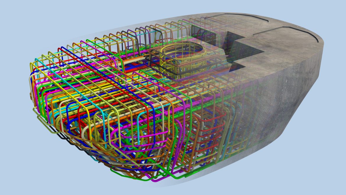
NS Drafter delivered 3D models and shop drawings for formwork and reinforcement of the upper and lower pier capitals that connect the precast viaduct sections to the supporting pillars. The work was carried out in Allplan, with reinforcement modeled directly within each precast element so that geometry, bar quantities, and placement logic stayed consistent across fabrication and installation.

Each pier capital was treated as a complete production unit. The model carried the formwork geometry, the embedded items, and the full reinforcement layout, which then drove the shop drawings used by the precast yard.
Challenges
The defining constraint on this scope was bar density inside the pier capitals. These elements transfer the full load of the elevated viaduct into the pillars, which means the reinforcement layout includes heavy main bars, dense stirrup confinement, and a series of embedded plates and anchor systems for the precast connections. All of it has to fit within a fixed concrete volume and still allow the bars to be placed, tied, and the concrete to be poured properly.
A second challenge was coordination between the precast pier capitals and the cast-in-place pillars. The starter bars and connection details had to align across two production environments, the precast yard and the construction site, with tolerances that work for both. Errors at this interface aren’t fixable on site once the precast element arrives.
Solutions
Modeling reinforcement directly inside each precast element in Allplan made it possible to review congestion zones in 3D before any drawing was issued. Bars were grouped, spacing was checked against placement clearances, and embedded items were positioned with full visibility of the surrounding reinforcement. What looked tight in the model was confirmed buildable before it reached fabrication.
For the connection interface, the model carried both the precast geometry and the corresponding pillar starter bar layout, so that the shop drawings issued for the precast yard matched the reinforcement drawings used on site. The same model fed both production environments, which is what kept the interface coordinated across 40,000+ tons of steel.
Precast Bridge Infrastructure Project
Overview of the Infrastructure Project
This infrastructure project involved reinforcement modeling and detailing for a precast concrete structure forming part of a bridge-related infrastructure system. The work was delivered in Tekla Structures, with reinforcement integrated directly into each precast element. The model functioned as the central source for fabrication drawings, layout documentation, and setting-out information used during production and on-site assembly.
Scope of Work
The deliverables covered the full chain from production to installation:
- Beam and slab setting-out plans
- Precast element distribution plans
- Fabrication drawings for beams and plates
- Detailed reinforcement drawings for precast elements

Each deliverable was generated from the same coordinated Tekla model, so that the geometry, bar marks, and quantities stayed consistent across documents.
Challenges
Precast bridge work has one technical constraint that defines everything else: once an element leaves the casting bed, it cannot be modified. The reinforcement layout, the embedded items, the lifting points, and the connection details all have to be correct on the first pour. Any error in the shop drawing becomes an error in the element, and the only options at that point are rejection or expensive retrofit.
The second challenge is distribution and assembly logic. Precast bridge elements arrive on site in a specific sequence and connect to other precast and cast-in-place components. The setting-out plans and distribution drawings have to support this sequence, which means the documentation has to be organized around how the elements get installed, not just how they get produced.
Solutions
Modeling reinforcement inside each precast element in Tekla allowed the team to align bar geometry, embedded items, and lifting hardware in one coordinated environment. Before any fabrication drawing was issued, the model was used to verify that bars cleared the embedded items, that lifting points had adequate cover and confinement, and that the connection reinforcement matched the geometry of the adjacent elements.
For the assembly side, the setting-out plans and distribution drawings were generated from the same model, which kept element marks, dimensions, and orientation consistent across all documents.
The shop drawings the precast yard worked from and the layout drawings the site crew worked from carried the same data, generated from the same source. That alignment is what reduced shop queries and kept production sequencing predictable.
Metro Station Infrastructure Project
Overview of the Infrastructure Project
This infrastructure project involved reinforcement modeling for a complex underground metro station delivered under active construction conditions. Unlike a typical design-then-build sequence, the model had to evolve in parallel with the work happening on site. Design changes, construction sequencing adjustments, and site-driven decisions were continuously integrated into the model so that reinforcement could be reviewed, adjusted, and redistributed without interrupting construction progress.
The workflow followed a BIM2Field approach, meaning the model wasn’t created only for coordination, it was developed as a practical tool that could be used directly on site through platforms like Trimble Connect.
Scope of Work
- Reinforcement modeling in Tekla Structures
- Preparation of structured deliverables for construction use
- Export of coordinated documentation in IFC, PDF, ABS, and DWG formats
- Organization of deliverables according to construction phases

The deliverables were structured so that each construction phase had its own coordinated documentation set, accessible to site teams through Trimble Connect alongside the underlying model.
Challenges
Underground metro stations bring constraints that surface infrastructure doesn’t have.
Geometry is fixed by the excavation method, not by the designer’s preference. Service tunnels, ventilation shafts, equipment rooms, and platform slabs all share a confined volume, which means reinforcement layouts run into clashes with embedded MEP, waterproofing details, and structural connections that wouldn’t appear on a typical building project.
 The bigger challenge was continuous change under active construction. Site conditions, contractor feedback, and design adjustments came in regularly, and the model had to absorb them without breaking the documentation chain. A change to one wall reinforcement layout couldn’t take a week to propagate, the site was already pouring the next pour.
Solutions
The BIM2Field workflow was the answer to both problems. By keeping the Tekla model as the single coordinated source and pushing updates through Trimble Connect, site teams worked from current information instead of marked-up PDFs from two revisions ago. When a reinforcement layout was adjusted, the change was visible in the model the same day, and the corresponding shop drawing, IFC, and DWG exports were regenerated from that source.
This is also where direct site experience changed how the work was done. Members of our team spent time on active construction sites with contractors, observing how shop drawings get used in practice, where bars are tied, how formwork is stripped, where installers run into problems that don’t show up in clash detection. What we saw on site fed back into how we modeled and how we structured the deliverables. A drawing that’s technically correct but hard to read under site conditions costs more time than a slightly less detailed drawing that crews can interpret in 30 seconds. The model gives the geometry, but the documentation has to give the build logic.
That feedback loop, between the model, the deliverables, and the people actually placing the bars, is what made the BIM2Field workflow function.
For more on how field experience shapes detailing decisions, see our blog 10 Powerful Insights from the Field.
Key Takeaways from These Infrastructure Projects
Three infrastructure projects, three different production environments, but the underlying principle is the same: on infrastructure projects, the model has to carry production-ready information, and the documentation has to carry build-ready logic. Anything less means the work gets reinterpreted somewhere downstream, in the precast yard, on the construction site, or during phase coordination, and that reinterpretation is where most infrastructure delays come from.
A few specific lessons from these projects worth carrying forward:
The precast environment doesn’t allow shop drawing corrections after casting, because the only options once a defective element is cast are rejection or retrofit. That’s why reinforcement modeling inside the precast element, not after it, is the only workflow that scales.
Connection interfaces between precast and cast-in-place are where most coordination problems originate, and the only reliable solution is to model both sides in the same environment so that the shop drawings and the site drawings come from one source.
BIM2Field is a workflow, not a deliverable. It only works when the model stays current with site conditions and the exports actually reach the people doing the installation. A model maintained in isolation from the site stops being useful within weeks.
FAQ
Q: What makes rebar detailing for infrastructure projects different from buildings?
A: Infrastructure projects deal with much higher reinforcement tonnages, more complex precast and cast-in-place interfaces, and construction phasing that’s often tied to active operations. The detailing has to support fabrication, installation, and phase coordination at the same time, which means the model carries a higher information load than on a typical building project.
Q: Why is BIM2Field important for infrastructure projects?
A: BIM2Field connects the digital model directly to the construction site through platforms like Trimble Connect, so site teams work from coordinated 3D information instead of static drawings. This reduces interpretation errors, supports faster updates when conditions change, and keeps reinforcement placement aligned with the current state of the design.
Q: Which software is best for rebar detailing on infrastructure projects?
A: Tekla Structures and Allplan are both widely used. Tekla is strong for production-oriented modeling and BIM2Field workflows on metro, rail, and bridge projects. Allplan performs well on precast-heavy infrastructure, particularly where formwork and reinforcement are modeled together. The right choice depends on the project ecosystem and the downstream production workflow.
Q: How does precast detailing differ from cast-in-place detailing on bridges?
A: Precast elements are produced in a controlled environment and cannot be modified after casting, so the shop drawings have to be correct on the first pour. The reinforcement model has to account for embedded items, lifting hardware, and connection geometry that aligns with adjacent elements before fabrication begins.
Q: Why is field experience important for rebar detailers working on infrastructure projects?
A: Models can pass clash detection and still produce drawings that are difficult to install on site. Detailers who have spent time on active construction sites understand how bars are placed in confined zones, how formwork interacts with reinforcement, and what makes a shop drawing readable under field conditions. That experience changes how the model is built and how the documentation is structured.
Q: How does reinforcement coordination work between precast and cast-in-place elements?
A: The starter bars, embedded items, and connection geometry on both sides have to align within tolerances that work for two different production environments. The reliable approach is to model both sides in the same environment so that the shop drawings issued to the precast yard and the reinforcement drawings used on site come from the same coordinated source.
About Us
NS Drafter specializes in BIM modeling, rebar detailing, steel detailing and construction documentation for residential, commercial, and complex infrastructure projects. Our teams work across Revit, AutoCAD (ArmCAD), Tekla and Allplan, delivering models and plans depending on project requirements.
Working on a precast viaduct, metro station, or bridge infrastructure scope?
We deliver reinforcement models, shop drawings, bar bending schedules, and BIM2Field-ready documentation built around the production environment, the precast yard, the fabrication tolerances, and the construction sequencing your project actually runs on. Get in touch and tell us about the scope.
