
Autodesk REVIT – The next step in drafting
What is Revit?
Revit is the software developed by Autodesk, the same company that developed AutoCAD and many other engineering software tools in use around the world. Progressive use of this software gradually led to its embedding into daily activities of design processes in companies. This is a Building Information Modeling software or BIM. It is in use by structural engineers, architects, MEP engineers (mechanical, electrical, and plumbing), designers, and contractors.
Revit allows users to draw buildings and many other structures and their components in a 3D view. Revit is also great for creating 2D plans. The database of Revit Families is vast, and people can have access to almost every material that is used for constructing, designing, creating future models. A model is a virtual version of the building design. It describes the geometry of the model elements and captures the planned design and logical relationships between elements.
While working on the building model, Revit collects the information about the building project and coordinates this information across all other representations and views of the project. While working on a model, Revit can automatically coordinate changes made within the entire model structure – model views, drawing sheets, sections, plans, and schedules.
2D Drafting
Prior to the creation of the 3D model, a common easier option is to draw the 2D plan first. After that, the model can be further created step by step. Besides the fact that AutoCAD is considered the best drafting software for 2D models, Revit software includes some pretty cool tools for creating plans and turning them into the 3D model. AutoCAD provides basic geometry options. Therefore, these two software tools are leading tools in Engineering and Architecture.
Creating building plans should start with designing floor plans for a building. Knowledge in AutoCAD keyboard shortcuts is very useful for this step. Also, clicking on the Revit working screen is another option for work.
The good thing is that everything needed is in one place.
Before creating the floor plan, the first step is to place gridlines on the plan. Levels and grids help to define the project context and organize the design. Gridlines are important for coordination through the plan. With all gridlines in place, drawing of beams for objects within them can be highly facilitated. The vertical menu on the left side of the working screen provides various views in 2D and 3D versions. This can be really helpful in cases when the simultaneous work in up to four plane views on one screen if needed.
This menu provides managing each floor plane, structural plane, and elevations separately, and all the information on these planes are reachable. Every change on the plane, side view, or section is automatically updated for the entire model. That is very convenient for work.
There is also an option of work in these views for checking the positions of floors (height, level, width …). The line can be drawn for each level. Gridlines are helpful for the positioning of columns. Columns are located in crossing points of gridlines.

After drawing beams and columns, the floor can be developed by simply filling the place between gridlines (which represent beams). The procedure is the same for all types of construction materials (steel, concrete, wood). The combination of functionalities and content is highly important in work. For example, for drawing walls, clicking on the WALL segment in the top left part of the Revit working screen will provide everything in one place.
This can be done for every element of the building: floors, columns, beams, and many others.
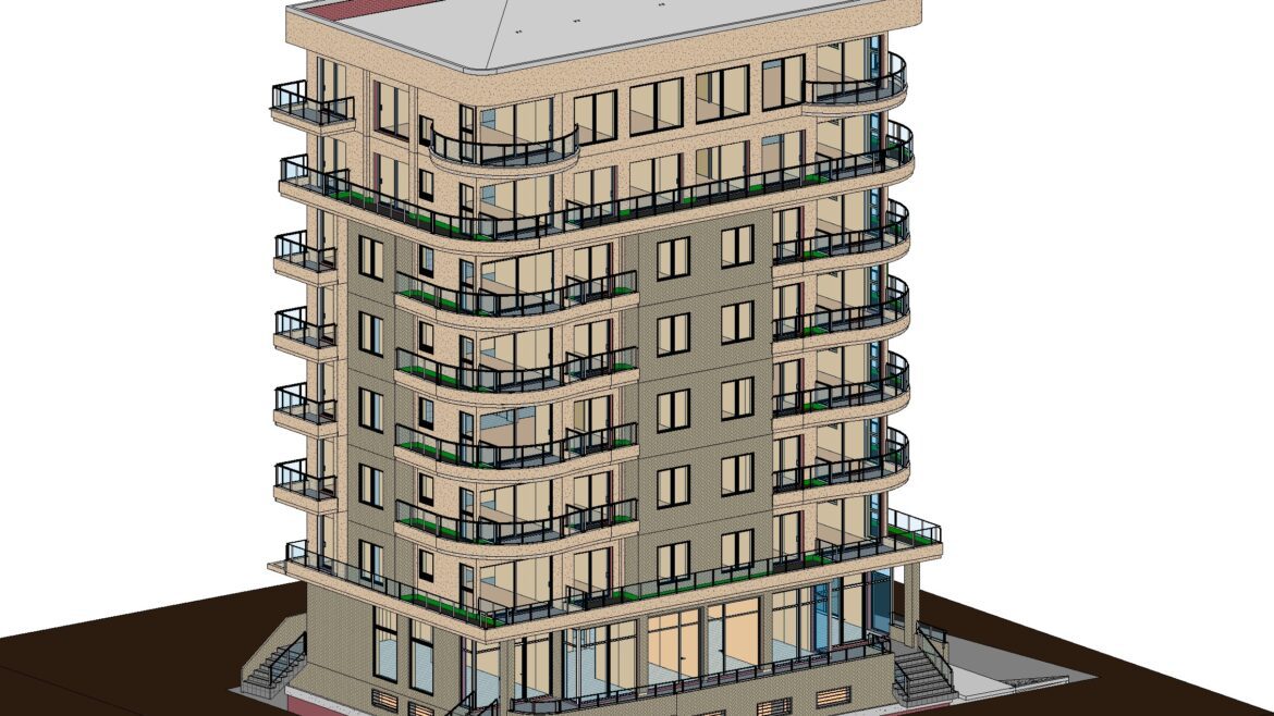
3D Modeling
This is where Autodesk Revit shows its full potential.
After finishing of main geometry structures of the object, everything can be seen in a 3D view. Holding the Shift button on the keyboard and pressing the Scroll button on the computer mouse at the same time provides the rotating of the object in any direction.

There are options of Zoom in and Zoom out. This provides the possibility to check if all elements are in their place. Details in Revit are in high-quality resolution, and zooming can provide the effect like the object is located right in front of people.
Revit includes big storage of construction materials sorted in Families, and they can be seen in detail in 3D views. Zooming in can easily show which material is used for each element. For instance, in work with steel beams, joints can be checked and rotated for finding anything incorrect in the section or detail. All of the actions during work will be automatically updated on the 3D model.
When working with concrete structures, rebar reinforcement can be drawn within the section. After finishing, it is possible to see them in a 3D view. That is very helpful in work with complicated walls. While using walls with changeable thickness or curves or non-symmetrical shapes, this option is highly useful. Slanted walls are also one of the great features of the Revit. Although this process was a challenge in earlier versions of Revit, the newer version made it possible! Wall can be created as slanted by changing the cross-section parameter in the Properties Palette.
Situations with openings in the concrete wall or floor slab can be a bit complicated because of additional reinforcement around those openings. Since it is very hard to use only section plans for adding reinforcement, the 3D view is very helpful. In this view, the position of reinforcement can be seen from any side while rotating the element. Rebar reinforcement in concrete elements includes various options for stirrups, rebars, their position, quantities, etc. The properties tab on the right side of the working screen is useful for selecting the desired types, dimensions, and positions of these elements.
Regarding this, every other situation with complicated shapes of walls or any other construction elements can be solved using the 3D view to look around the object and see what is going on there. Above all, the simplicity of Revit provides the possibility to have all project information in one place. One of the usual options is placing text annotations for each element in selected views. Each kind of element (columns, beams, slabs, reinforcement elements) is defined in the Revit database. Thanks to the 3D view, rebars can be modified and rotated according to the position of the element.
Creating sheets, Rendering, and Walkthrough
Creating sheets in Autodesk Revit is not complicated. The main step is to move existing sections and details to the sheet and put them in the right scale.
In case of adding some details which were not added earlier, the main action is to create a viewport in the model and move it to your sheet. Viewports in the 3D view can also be created and added to the sheet.

Rendering is another nice feature of Revit, and it is located in the View tab. Before Render starts with work, it is possible to choose what kind of picture the user/drafter wants (draft or medium, high, the best quality of the picture). The AutoCAD keyword command – WT includes connecting two views on the working screen.
It is possible to set the resolution, background, and desired kind of light and view angle. After setting all mentioned, it is time to click the Render button. The time of rendering depends on the user’s computer specifications.
Revit 2021 provides real-time realistic views, material appearances, and lighting effects to the view as the user moves through the model.

The last but not least feature is the Walkthrough option.
It means it is possible to move through the building or around it. This is a very nice feature for making a presentation of your object. All that needs to do is to click on the Walkthrough tab and draw the line which presents the path of the camera.
The user can change the speed, height, and angle of the camera along the path line. This is just another feature of Revit, which helps users to view their objects from all sides, inside and outside.
Autodesk Revit is very easy for use, especially for 3D modeling. It has many options and huge storage of materials and information that are needed for creating buildings or any other type of object. It is very handy for engineers and architects. Thanks to the Autodesk Cloud system, more people can work on one project at the same time. It is very useful in terms of saving time and money for structural design processes.
