
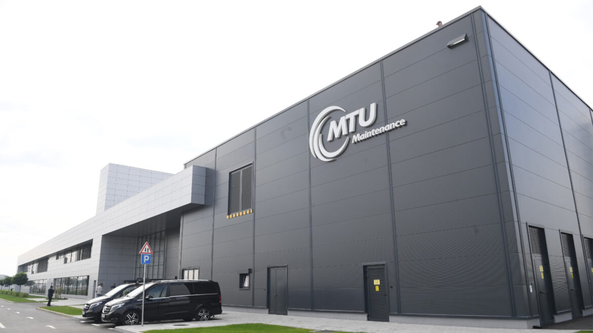
Successful Construction Case Study I MTU Nova Pazova
Overview
Industrial building BIM rarely means one structural system. A manufactory and an office building don’t usually share a roofline. One needs a clear span wide enough for production equipment; the other needs a repeatable floor grid, stairs, and corridors. The MTU Nova Pazova project asked for both, in a single structure, coordinated as one building rather than two projects bolted together.
The facility covers approximately 30,000 m² and combines a large-format industrial production area with a separate administrative section.
The manufactory zone is an open-plan production hall, sized to accommodate industrial equipment and workflow rather than a fixed room layout. The administrative zone sits apart from it, organized across three levels, with each level built out across two to three floors depending on where it falls in the building’s footprint, a layout that keeps office and corridor space efficient without pushing the building’s overall height, but that also means the structural grid doesn’t repeat identically from one part of the administration block to another.
Project Info
- Location: Nova Pazova, Serbia
- Facility type: Multipurpose manufactory with integrated administrative offices
- Total area: 30,000 m²
- Building zones: Manufactory (open production space) + Administration (3 levels, 2–3 floors per level depending on position)
- Software: Autodesk Revit
- Quality control platform: Autodesk BIM 360 (Autodesk Construction Cloud)
- Completion: 2021
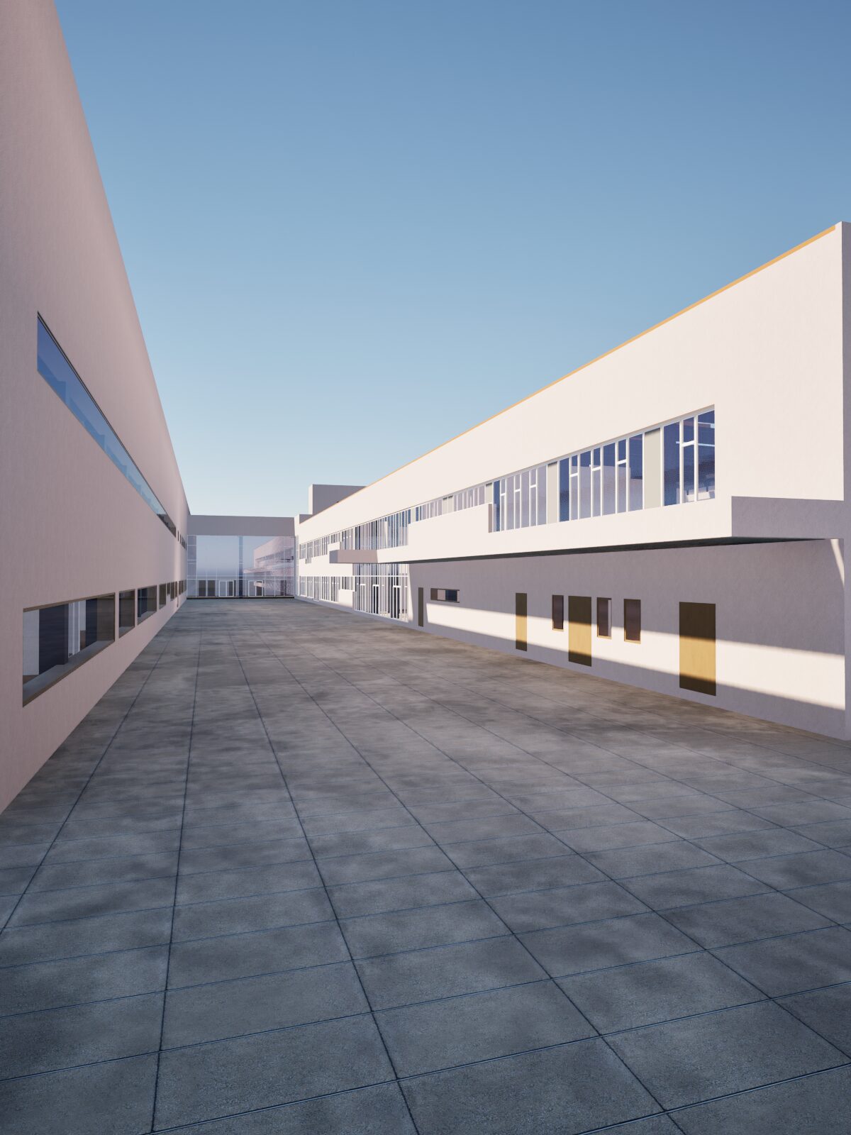
That combination, one long-span production volume and one variable-height office block, in the same coordinated model is what made this project a genuine BIM coordination exercise rather than a straightforward architectural build-out.
Scope of Work
NS Drafter was responsible for the structural and architectural 3D model of the facility, built in Revit, along with the visualizations used to support project planning and stakeholder presentation. The brief covered both functional zones of the building, but the structural system carried particular weight in the modeling effort.
Specific focus areas included:
- Beams, columns, and floor structure across both the manufactory and administrative zones
- Roof structure, sized and detailed differently for the production hall than for the office block above it
- Spatial organization of the administrative section’s variable floor counts, so the model reflected the building’s actual layout rather than a simplified, uniform version of it
- Visualization output for internal planning reviews and client presentation, built directly from the coordinated model rather than produced as a separate rendering exercise
 Workflow
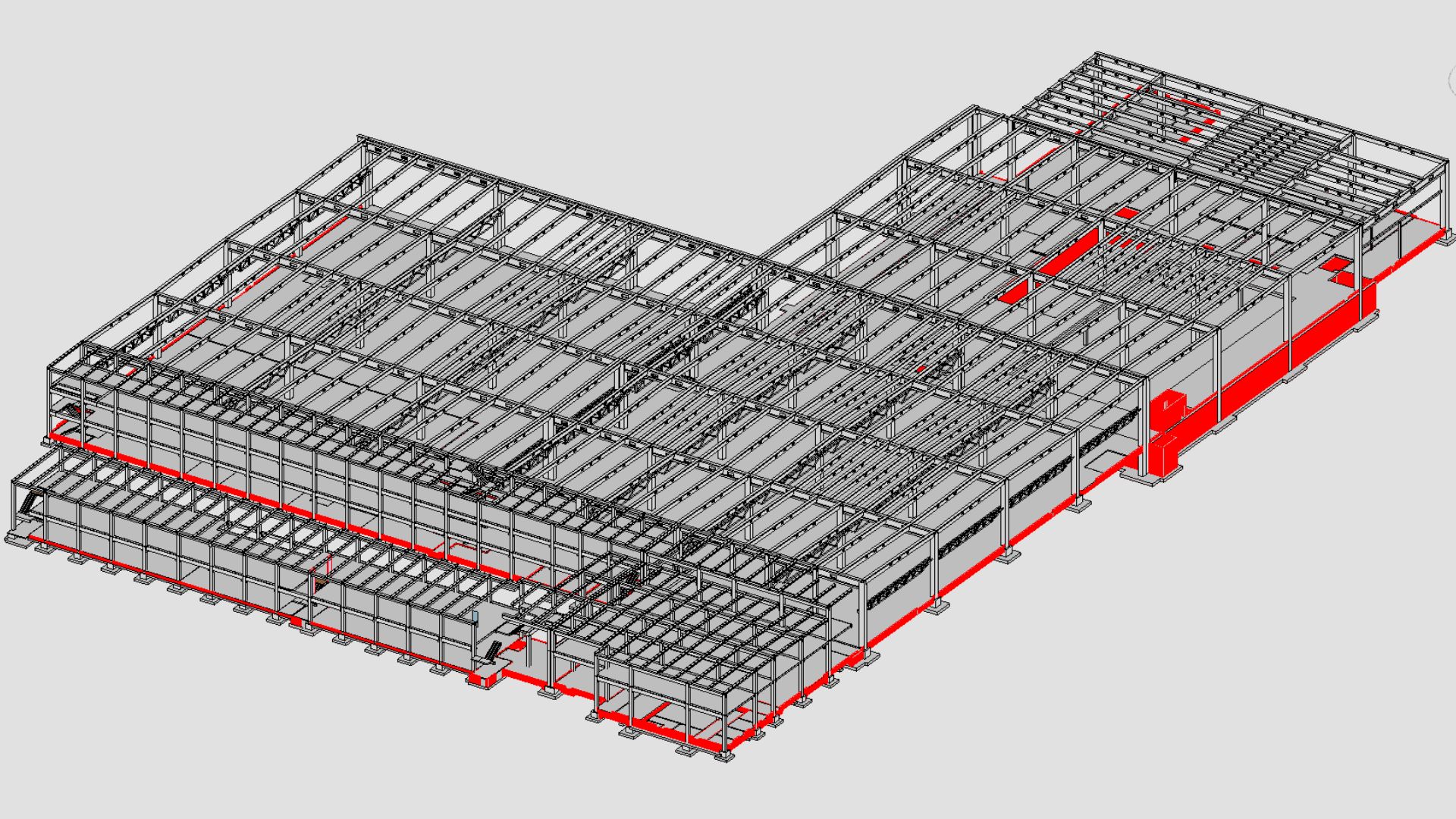 Workflow
The industrial building BIM approach treated the manufactory and administration zones as one coordinated Revit environment. That decision shaped most of the workflow downstream.
Structural elements were modeled first – columns, beams, and floor plates – establishing the grid each zone would build on. Because the production hall and the administrative block behave differently at a structural level (one prioritizes clear span, the other prioritizes repeatable floor-to-floor height), the grid strategy had to accommodate both without forcing an artificial alignment between them. The roof structure was modeled zone by zone, since the production hall’s roof geometry has little in common with the roof condition over a three-level office block.
Architectural elements like walls, openings, circulation, and the administration block’s floor-by-floor layout, were built on top of that structural base once it was confirmed.
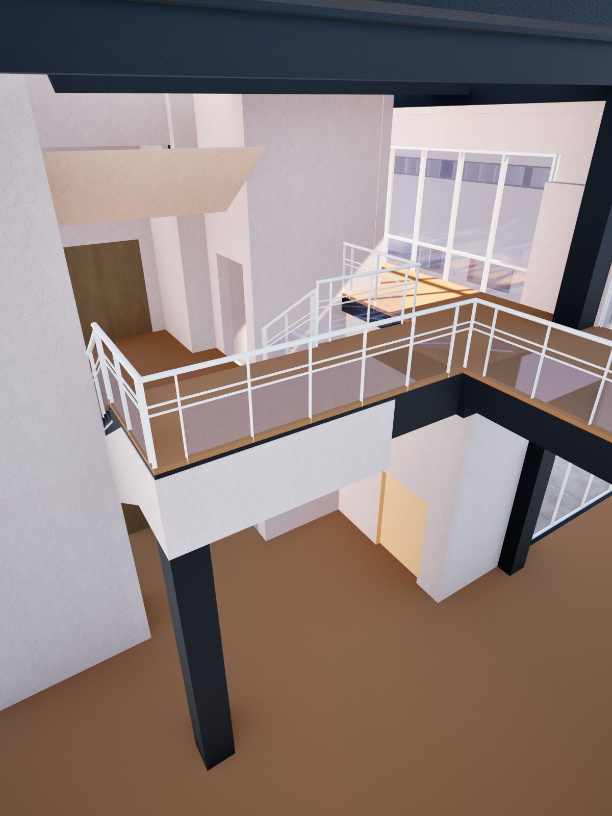
Visualizations were generated directly from the model at key milestones, giving the project team a way to review spatial organization and structural intent without waiting for a separate rendering pass. Because the renders came from the same model used for structural documentation, there was no risk of the visualization drifting from what the structure actually was, a common problem when renders are built as a parallel, disconnected exercise.
Quality control ran through Autodesk BIM 360 for the project’s duration, using its Issue Management module to log, assign, and close out coordination items as they came up, rather than tracking them through email threads or marked-up PDFs.
Two Structural Systems Under One Roofline: Industrial Building BIM in Practice
The manufactory and administration zones had to read as one building while being modeled with two different structural logics. Below, each challenge runs straight through to its solution and result.
A Long-Span Hall Meeting a Repeatable Office Grid
The production hall needed a column-light open span for equipment; the administration block needed a repeatable structural grid.
The grid was established zone by zone before any architectural modeling, treating the two as distinct systems that meet at a defined interface. The production hall’s roof was modeled independently, so its long-span framing wasn’t constrained by office-section assumptions. The result: structural documentation for beams, columns, floors, and roof framing that’s consistent across both zones, from a model where the two systems were resolved against each other rather than reconciled later.
The Administration Block’s Variable Floor Counts
The office floor count changes across the footprint, so beams, columns, and floor plates can’t be copied uniformly – the kind of condition that produces mismatched levels or columns that don’t land on a floor plate.
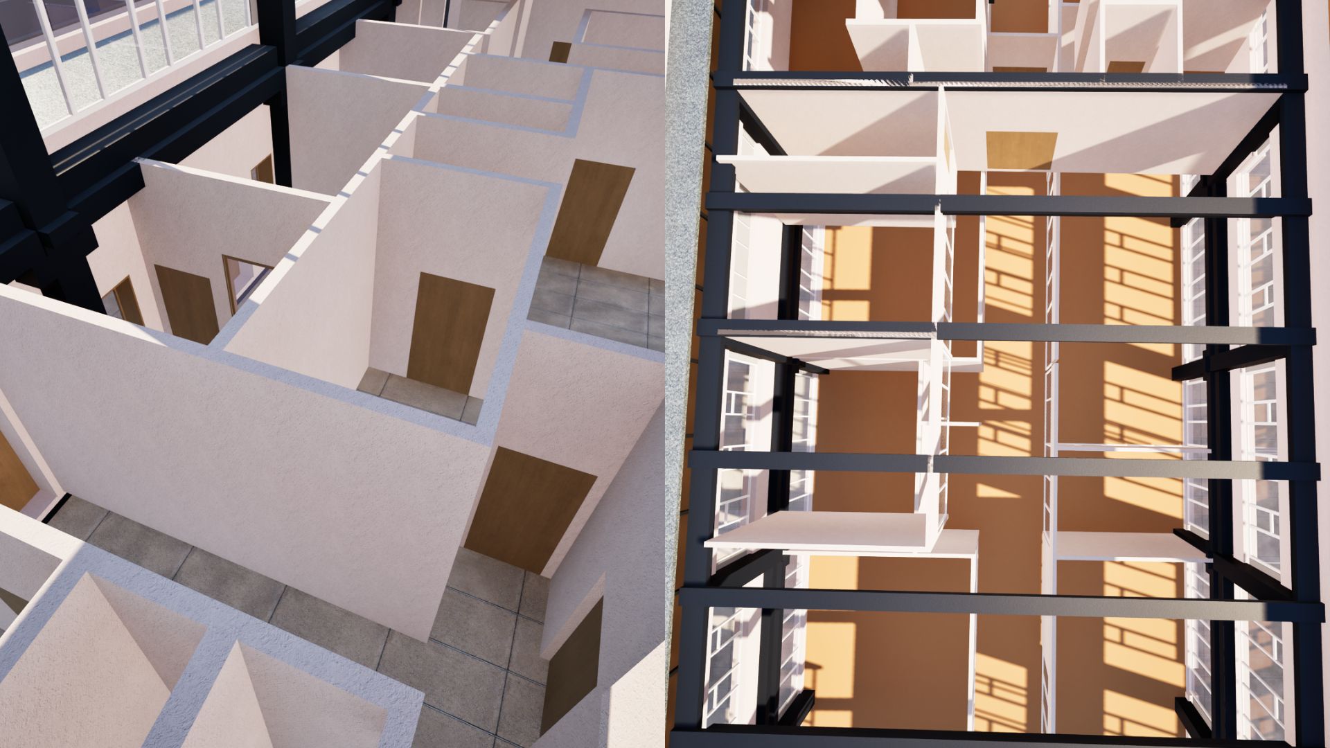 Levels were set up in Revit so each portion referenced its correct local level structure, letting elements land correctly without manual overrides section by section. As a result, the variable floor counts are represented accurately rather than simplified – which matters directly for construction sequencing, so a contractor isn’t discovering mid-build that a section differs from the rest.
A Clean Zone Interface and Trackable Coordination
The two sections needed clear functional separation while behaving as one building for load path, drainage, and circulation – the biggest source of potential coordination error.
Coordination issues were logged and tracked through Autodesk BIM 360’s Issue Management for the project’s duration, with every open item owned and visible to the full team rather than buried in email or marked-up PDFs. Visualizations from the same model gave stakeholders an accurate view of the building’s spatial organization without a separate rendering process to keep in sync.
Key Takeaways
- Mixed-use industrial building BIM needs one coordinated model, not two. Modeling a production zone and an administration zone as separate efforts and reconciling them at the end is exactly how zone-interface clashes get missed until construction.
- Variable floor counts across a single footprint are a real coordination risk, not an edge case. If a building’s administrative section doesn’t have a constant number of floors throughout, the level structure in the model has to account for that from the start, not get patched in later.
- Structure before architecture is a sequencing decision, not a formality, especially when a building mixes a long-span industrial structural system with a conventional multi-story grid.
- Centralized issue tracking pays off most on projects with more than one structural logic in play – the more moving parts a building has, the more value there is in a single, visible record of what’s been flagged and resolved.
FAQ
Q: Why does an industrial manufactory need the same industrial building BIM attention as an office building?
A: Because the two zones don’t share a structural system, and treating them as one simplified model risks exactly the kind of clash – mismatched levels, misaligned columns – that’s hard to catch after the design is frozen. The production hall’s long-span framing and the administration block’s multi-floor grid each need to be modeled on their own terms, then coordinated at the interface.
Q: How do you model a building where the number of floors changes across the footprint?
A: By setting up the level structure locally for each section of the building rather than applying one uniform set of levels across the entire footprint. On MTU Nova Pazova, the administration block’s three levels break down into two to three floors depending on position, so the Revit level setup had to reflect that variation directly instead of forcing a single grid over an uneven condition.
Q: What does BIM 360 Issue Management actually add on a project like this?
A: It gives every open coordination item – a clash, a discrepancy between the structural and architectural model, a question that needs an answer before modeling can continue – an owner, a status, and a visible history.on a project with two distinct structural systems, that visibility is what makes industrial building BIM coordination work.
About Us
NS Drafter specializes in BIM modeling, rebar detailing, steel detailing and construction documentation for residential, commercial, and complex infrastructure projects. Our teams work across Revit, AutoCAD (ArmCAD), Tekla and Allplan, delivering models and plans depending on project requirements.
Our Project Case Studies:
Successful Construction Case Study I Tesla Gigafactory Berlin
Successful Construction Case Study I 55.000 m² in Amsterdam
