

Tekla Custom Components: The Complete Automation Guide
The Real Fork in the Road: Copy-Paste or Automate?
Every Tekla modeler eventually hits the same fork in the road: keep copying and pasting connection details detail by detail, or invest time in building or properly configuring a Tekla custom component that does the repetitive work automatically. Both approaches are legitimate. The real skill is knowing which situations justify the switch from manual repetition to automation.
This guide covers what Tekla custom components actually are (they’re not one tool, they’re four), how to get more out of the components Tekla already ships with, how to build your own when the built-in library doesn’t cover your standard details, and what actually determines whether that investment is worth it.
What Are Tekla Custom Components, Really?
A “custom component” in Tekla is a family of tools, each built for a different modeling situation.
Picking the wrong type is one of the most common reasons a component ends up unreliable or hard to maintain.
Tekla custom components ≠ One Tool
A common confusion: people use “custom component” to mean any parametric object in Tekla, but the four types behave differently under the hood and aren’t interchangeable. Using a Connection where a Seam is actually needed, or vice versa, is a frequent source of components that “mostly work” but break on edge cases.
- Connection – Attaches one part to another (a beam to a column, a brace to a gusset, a base plate to a footing). This is what most people mean by “custom component.” It understands the relationship between a main part and one or more secondary parts.
- Detail – Works on a single part rather than a connection between two parts. Typical uses: end plate copes, stiffeners, notches, or reinforcement details applied to one member.
- Seam – Creates connection objects (plates, welds, bolts, or reinforcement) along a defined line between parts, rather than at a discrete joint between a main and secondary part. This makes Seam the right tool for splices, but also for other conditions where the connecting geometry runs along an edge or interface rather than being anchored to one “main” part. It’s defined by the line the connection follows, not by whether the two parts happen to be the same type.
- Part – Generates entirely new geometry rather than modifying or connecting existing objects. Useful for stairs, ladders, handrails, or repetitive precast elements placed as a single parametric object.
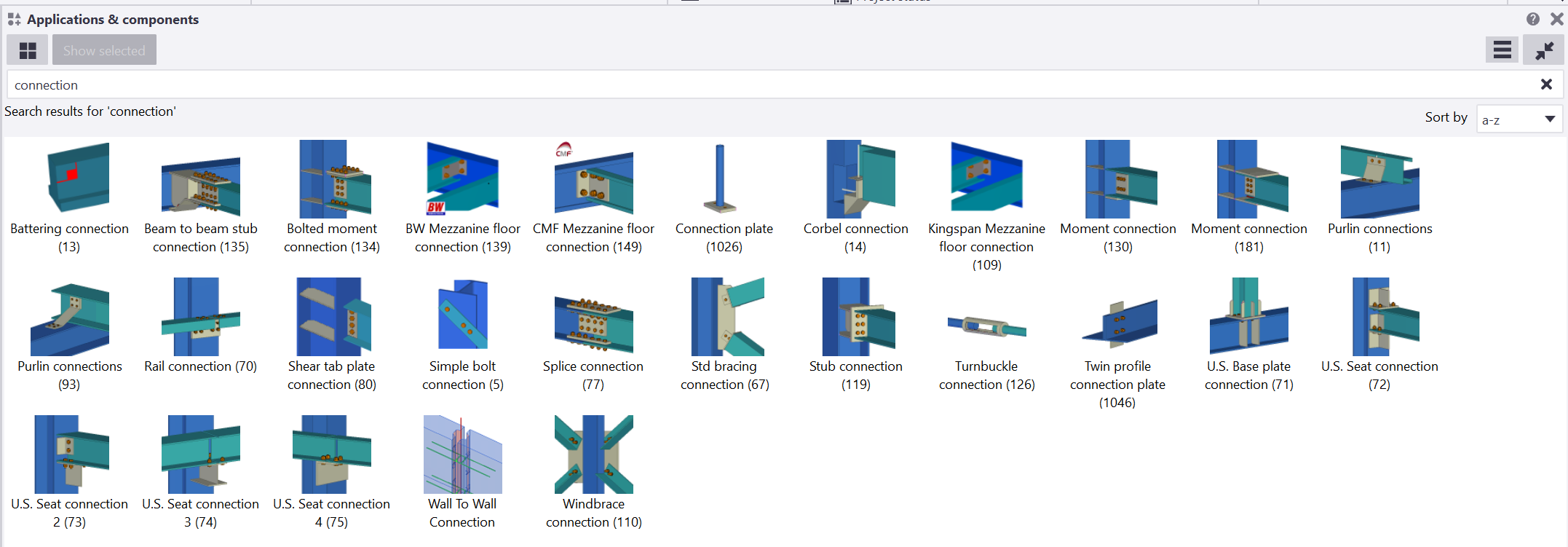 Tekla’s built-in library covers all four types – steel connections (shear tabs, moment connections, base plates, bracing gussets), concrete and precast connections, reinforcement components (beam and column reinforcement, mesh, stirrup groups), and detailing components (copes, notches, stiffeners).
These are pre-built, widely tested, and cover most standard situations, but they’re generic by design.
That’s exactly where presets and customization come in.
Getting More Out of the Built-In Library: Presets
Before building anything custom, it’s worth squeezing everything possible out of the components Tekla already provides, because most modeling inefficiency doesn’t come from missing functionality, it comes from re-entering the same settings over and over.
Common examples:
- Shear tab / fin plate connections – bolt size, edge distances, plate thickness, weld size.
- Base plates – plate dimensions, anchor rod layout, stiffener configuration, grout thickness.
- Bracing/gusset connections – gusset shape, bolt pattern, clip angles.
- Reinforcement components (stirrups, longitudinal bars, mesh) – bar diameter, spacing, cover, hook types, the same values that drive waste when they’re re-entered inconsistently across a project, as we’ve covered in .
On a repetitive structure, a multi-bay portal frame, a parking structure with dozens of near-identical columns, a precast building with the same beam-to-column joint repeated fifty times, typing these values manually every time is where most modeling hours get lost, and it’s also where mistakes creep in.
One bolt-spacing typo repeated across forty connections is a real problem to catch after the fact, as anyone who has worked a project on the scale of our will recognize.
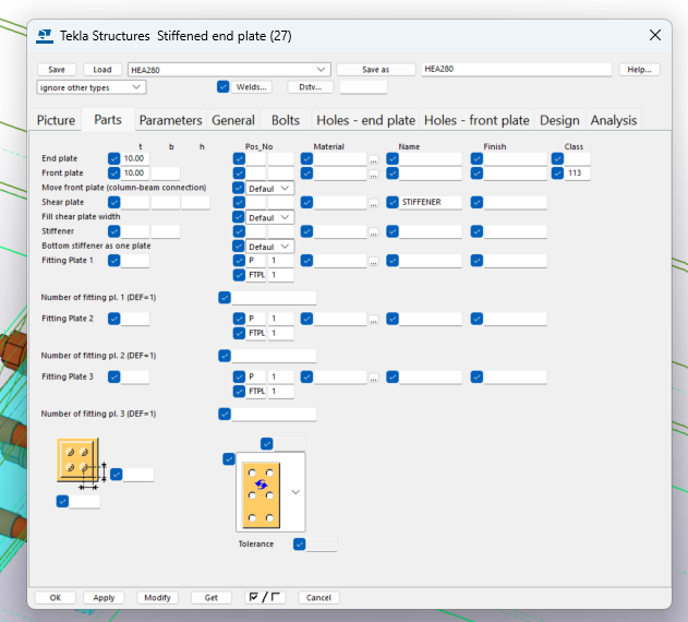
This is exactly what saved settings, or attribute presets, solve. Configure a component correctly once, save it as a named preset, and load it the next time you need the same connection logic, even on elements with slightly different profile sizes or angles.
On repetitive structures, this alone is often the single biggest time saver available without writing any custom logic at all.
Building Your Own Tekla Custom Components
Presets solve repetition of settings. Sooner or later, though, you’ll hit a connection type the built-in library simply doesn’t cover – something specific to your company’s standard details, or a reinforcement arrangement governed by an internal design table rather than a generic parametric rule.
That’s when building a custom component from scratch, or heavily modifying an existing one, is worth the investment.
Start From Your Construction Album
If your office works from a book of standardized connections (common in precast and industrial steel design), each detail usually already has defined rules: for a given load or span range, use this plate thickness, this bolt arrangement, this anchor count. That table is your specification before you open the component editor.
Model the Base Geometry
Build the connection parametrically in the Custom Component Editor using standard Tekla objects (plates, bolts, welds, cuts), with UCS-driven positioning so the geometry adapts to different part sizes and orientations rather than being fixed to one case.
Expose the Parameters That Actually Vary
Plate thickness, bolt diameter, bolt spacing and arrangement, number of rows, stiffener presence — these become component input fields rather than hardcoded values.
Decide How Those Parameters Get Their Values
This is where a construction-album-based component earns its keep, and it’s also the step worth being precise about, because it’s not something a standard parametric custom component does automatically out of the box.
A plain Tekla custom component built in the graphical Custom Component Editor exposes parameters and lets the user, or a saved preset, set their values – it doesn’t natively read an external file. Having a component pull plate thickness, bolt arrangement, or similar values from a design table stored outside the model is possible, but it isn’t out-of-the-box behavior: it requires additional implementation, typically through the or a separate workflow that feeds the looked-up values into the model before the component runs.
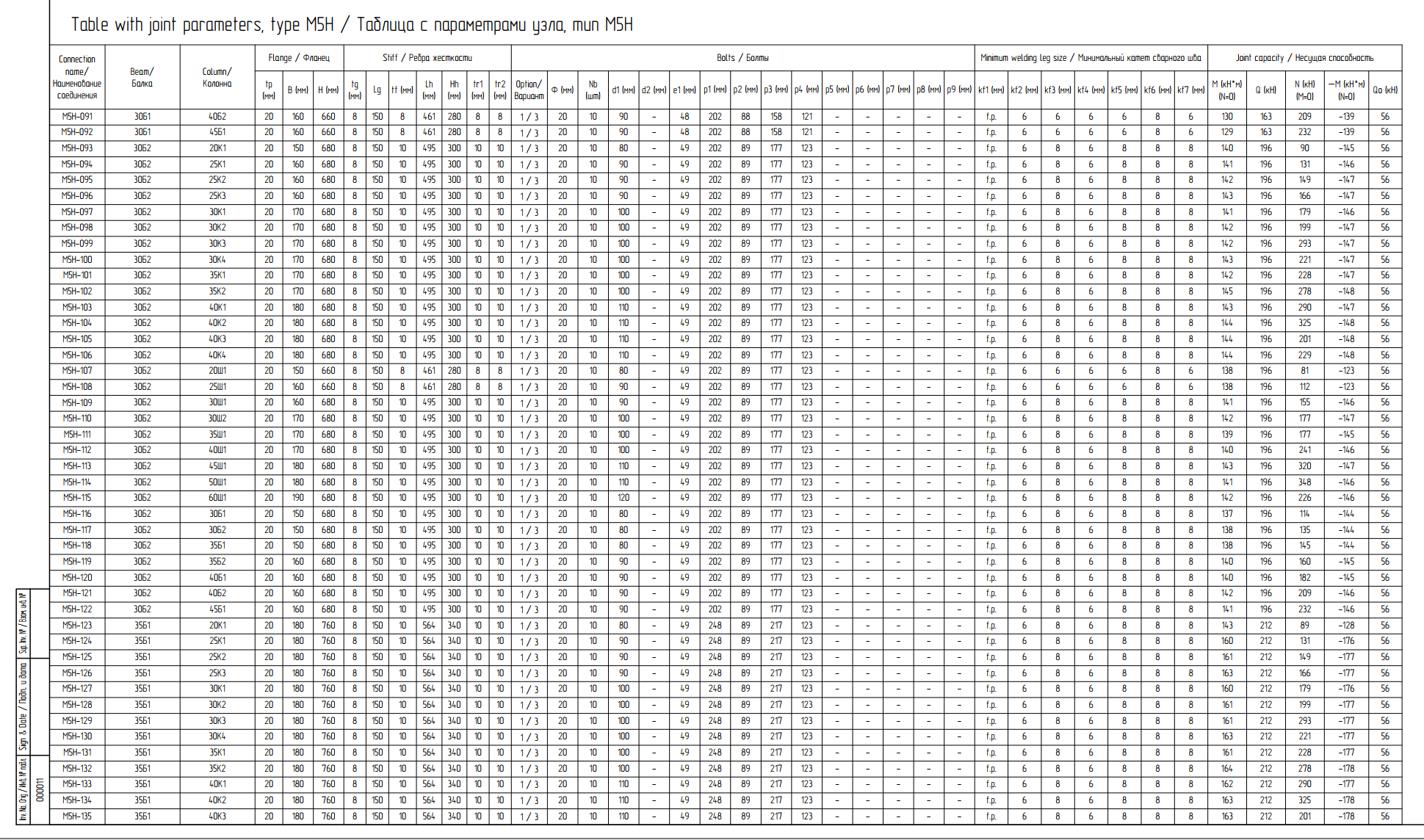
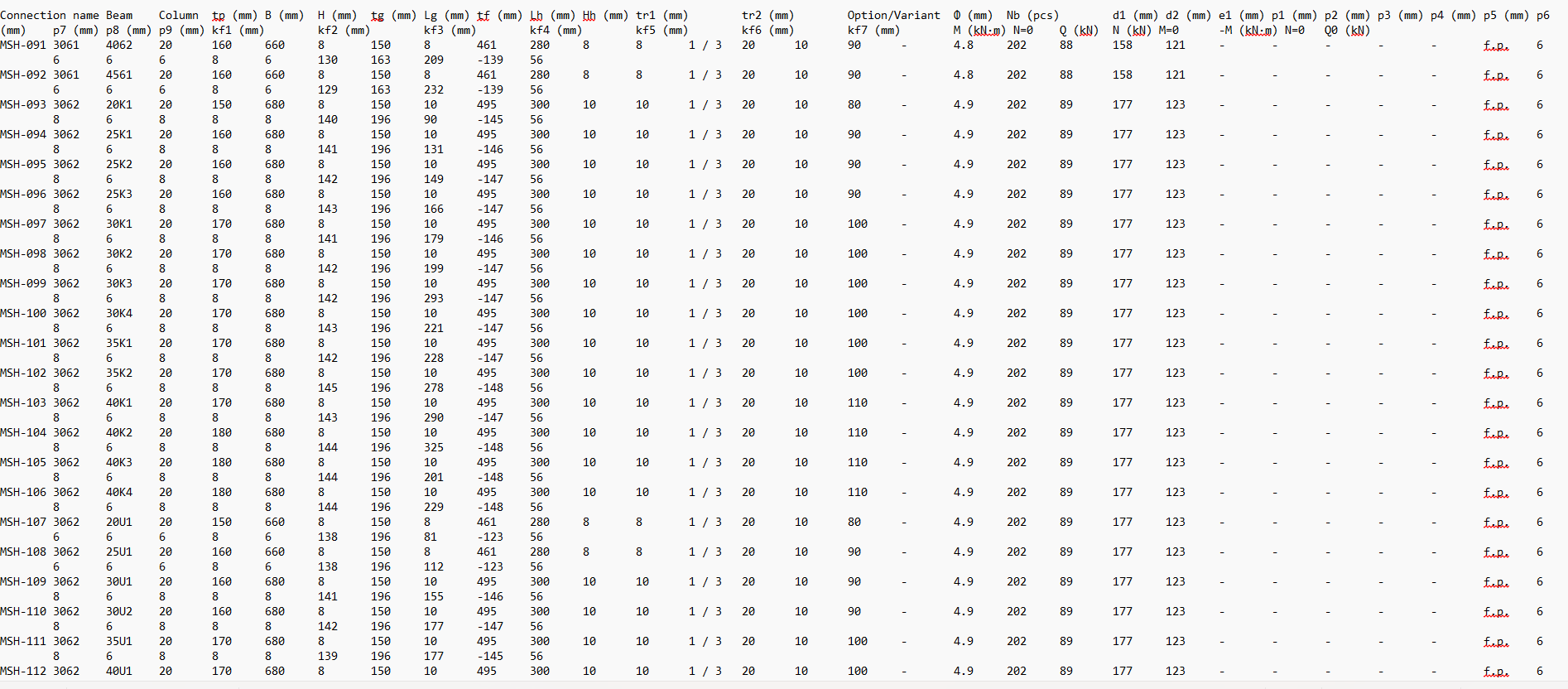 The same discipline that keeps a tied to code tables rather than rules of thumb applies here: the component’s job is to place and size geometry correctly, not to recalculate a value that engineering has already determined.
Maintain the Table, Not the Component
When your design tables get revised, a new code edition, an updated standard detail, you edit the external table. You don’t touch the component’s placement logic, which keeps the component stable and keeps the design data centrally controlled and auditable by an engineer, not buried in component code.
Done this way, the custom component behaves as a lookup-and-place tool rather than a calculation engine, faster to verify, and far easier to hand off or revise than a component that tries to reproduce a design calculation internally.
Tools We Use
At NS Drafter, this workflow runs almost entirely inside Tekla Structures: the Custom Component Editor for geometry and parameter exposure, saved attribute presets for repeatable settings, and the Tekla Open API layer when a component needs to read from an external lookup table rather than accept manually entered values.
Keeping the design data in a maintained external table, rather than hardcoded inside the component, is the same information-management discipline behind standards like – the value lives in one governed place, and the model consumes it rather than duplicating it.
NS Drafter Experience
We build lookup-driven components most often on precast and repetitive steel projects, where the same detail, governed by the same construction album, repeats across dozens or hundreds of instances. The pattern we’ve seen hold up project after project, and it’s the same logic behind our : the model should stay a faithful representation of a decision made elsewhere.
Choosing the Right Level of Automation
Not every repetitive connection needs the same amount of engineering effort behind the component. In practice, the right level tends to fall into one of three categories.
A preset for a connection that already exists.
If the connection type is already covered by the built-in library or an existing component, and only the settings change between instances: plate thickness, bolt size, spacing – a saved preset is all that’s needed. No new logic required.
A lookup-driven component tied to one design table.
If a construction album or internal standard already governs the connection, the component’s job is to read the correct values and place them, not to calculate anything. This is the case described above, and it’s worth the setup once the connection repeats enough to justify building and maintaining the lookup logic.
A fully parametric component with internal calculation logic.
Reserved for connections where the sizing genuinely varies continuously rather than in discrete steps from a table, or where the component needs to respond to live model data such as calculated member forces. This is closer to the kind of parametric design logic used in generative modeling tools, and it’s the most labor-intensive path – one that should be used deliberately.
There’s no universal rule for which category a given connection falls into. The right choice depends on how often the connection repeats and, just as importantly, on where the design values actually come from: a fixed table, a continuous calculation, or live model data.
Match the automation to the source of the data, not the other way around.
Conclusion
The strongest case for Tekla custom components isn’t “automation is always better.” It’s this: once engineering has already determined how a connection is sized, a plate thickness, a bolt arrangement, a reinforcement layout – the modeling task is to build a reliable base, expose only the parameters that actually need to change, and drive those parameters from the predefined configuration or data that already exists, rather than reconstructing the engineering logic as formulas inside the component simply because allows it.
That’s also why there’s no single right answer to “Tekla custom component or copy-paste.” The correct level of automation depends on how often a connection repeats, and on where the design data it depends on actually comes from. Get the base right, expose only what needs to vary, and let the source of the data, not the software’s capabilities, decide how much logic belongs inside the component.
FAQ
Q: Is a Tekla custom components always worth building instead of copy-paste?
A: No. For a connection that only appears once or twice, copy-paste or manual modeling is faster than building or configuring anything. The investment in a custom component only pays off once a connection repeats enough times that consistency and setup time start to matter.
Q: Can a standard custom component read values from an external file like a .txt table?
A. Not by default. Reading an external lookup table takes additional implementation, typically through the Tekla Open API or a separate workflow that feeds the looked-up values into the model, it isn’t native behavior of a standard graphical custom component.
Q: What’s the practical difference between a Seam and a Connection in Tekla?
A: A Connection is anchored to a main part with one or more secondary parts attached to it. A Seam creates connection objects along a defined line between parts, which is why it fits splices well but isn’t limited to parts of the same type, the defining factor is the line the connection follows, not the part types involved.
Q: Should the design table live inside the component or outside it?
A: Outside it, where possible. Keeping plate thicknesses, bolt arrangements, and similar values in a maintained external table, rather than hardcoded or calculated inside the component, means engineering can revise the table without anyone touching or re-testing the component’s placement logic.
