
Successful Construction Case Study I Tesla Gigafactory Berlin
Overview
Tesla Industrial Facility is one of the fastest and most demanding industrial construction projects. NS Drafter worked on the project as a subcontractor providing rebar detailing service and formwork documentation for prefabricated concrete elements. This is a breakdown of what that scope involved, what made each element technically demanding, and what the consequences of a single missed detail would have been.
Tesla Industrial Facility Berlin
- Location: Grünheide, Brandenburg, Germany
- Facility size: 300+ hectares
- Production capacity: 500,000 vehicles per year
- Structural system: Prefabricated reinforced concrete
- Construction period: Early 2020 – March 2022

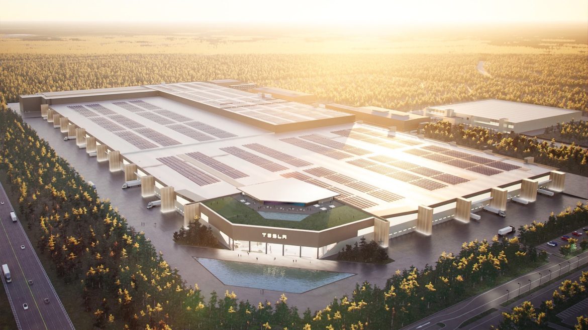
Aerial view of the Tesla Gigafactory Berlin-Brandenburg site, Grünheide, Germany. Photo: Raimond Spekking / CC BY-SA 4.0

The main production building is a single, continuous reinforced concrete frame. Stamping, body shop, paint shop, and final assembly occupy the same structure in sequence, without constructive separation between functions.
The load-bearing system runs almost entirely on prefabricated reinforced concrete: facade panels with insulated core for the building envelope, precast columns and beams carrying the vertical and horizontal loads, precast floor slabs, staircases, and podium structures throughout.
Every element fabricated off site and arriving according to a fixed delivery schedule.
Site preparation began in early 2020. The factory opened on March 22, 2022. Multiple construction phases ran in parallel to meet that date, which compressed every subcontractor’s delivery window to the minimum and eliminated any buffer for documentation errors.
Prefabrication was the logical structural choice for a project of this pace. Elements are cast while groundwork continues in parallel, and erection moves significantly faster than cast-in-place alternatives.
The technical consequence of that choice is that all engineering decisions, geometry, reinforcement, embeds, anchor positions, must be fully resolved before the mold is set. Once an element is cast, its dimensions and reinforcement layout are fixed.
Why Precast Detailing Carries Direct Cost
At the Tesla Industrial Facility, the molds, reinforcement cages, and casting beds were all tied into a single production sequence.
One wrong drawing forces the precaster to halt production on dependent elements, disrupts the fabrication schedule across an entire batch, and pushes costs well beyond the value of the element itself.
On a project where multiple construction phases ran in parallel, documentation delivery windows were fixed. Every subcontractor operated at the absolute minimum of schedule buffer.
A drawing error means fabrication downtime, a broken sequence across an entire element batch, and a rescheduled delivery that has nowhere left to shift.
The drawing is the only point in the process where a mistake can still be corrected at no cost. Everything after that carries a direct price tag.
The structural system was almost entirely prefabricated. Each element was delivered as a single package to the plant: 2D shop drawings, bar bending schedules, and a 3D reinforcement model.
The factory now employs around 12,000 people, and the roof is set to become one of the largest solar installations in Europe, as part of Tesla’s broader energy strategy for the plant.
Scope of Work
Our scope on the Tesla industrial Facility Berlin covered reinforcement and formwork models and drawings for prefabricated reinforced concrete elements across the entire structural system. The modeling and detailing were carried out in Allplan.
Prefabricated Roof Panel
- Size: 8.25 × 3.05 m | Thickness: 20 cm |
- Weight: 11.90 tons | Reinforcement: 750 kg
- Features: ventilation opening, 1.5° slope

A 1.5° slope has to run consistently through the formwork geometry, the reinforcement layout, and the anchor positioning. A panel documented as flat but cast with a slope won’t sit correctly on its supports and that’s not something you fix on site.
The embedded hardware consists entirely of transport and mounting anchors. Transport anchors are positioned symmetrically relative to the center of mass, at one quarter of the longer dimension on the flat long side.
The four mounting anchors are arranged on the upper face along the circumference of a circle centered on the element’s center of gravity, the geometry that allows the panel to be lifted level and placed without adjustment at height.
That positioning is calculated from the actual mass distribution of this specific element, not taken from a standard detail.
Prefabricated Wall with Large Structural Opening
This prefabricated wall carried the highest reinforcement density in this scope. A large structural opening cuts through a substantial portion of the cross-section, which shifts significantly higher stress onto the bars running along the opening perimeter.

The corners are the critical zones, that’s where cracking initiates if confinement and diagonal reinforcement are insufficient.
The 3D reinforcement model was built before the 2D shop drawings to verify bar arrangement at the opening corners. At this level of bar density, a flat drawing cannot confirm that everything fits.

Formwork drawings were developed in parallel, with opening geometry, panel thickness, and reinforcement cover cross-checked across both document sets before issue. A mismatch between the reinforcement plan and the formwork drawing at this production pace costs the precaster fabrication time that can’t be recovered.
Staircase with Integrated Landings
- Horizontal span: ~6 m | Rise: 2 m |
- Weight: 6.8 tons | Reinforcement: 420 kg

3D concrete model of the staircase element, cast as a single monolithic unit with integrated landings, horizontal span ~6 m, weight 6.8 tons

The staircase was cast as a single monolithic unit with the landings on both sides.
The landings bear on reinforced concrete beams once installed, the reinforcement layout accounts for that bearing condition from the start.
The detailing problem on this element was the load angle at each anchor during lifting. Staircase geometry means the lifting force doesn’t act vertically relative to the anchor axis. The resultant pulls at an angle, and the anchor zone reinforcement has to be designed for that actual angle.

Transport anchors are placed on both longer sides, two per side, with anchor zone reinforcement calculated from the real lifting geometry of this specific element.
For each element, anchor positioning was resolved individually:
Center of mass and center of gravity verified per element, not carried over from a similar element
Anchor zone reinforcement designed for the actual lifting geometry, including the specific load angle
Lifting angle treated as the governing parameter, on the staircase, it directly determines the local reinforcement demand

Conclusion
Tesla Gigafactory Berlin operated under conditions that defined the entire scope – 300+ hectares, 500,000 vehicles per year, a fixed opening date. Every prefabricated element had to arrive on site exactly when planned and in exactly the geometry defined in the documentation.
All engineering decisions had to be fully resolved before the mold was closed, because after that the element is fixed and what the drawing says goes into the concrete.
That constraint defines what matters in prefabrication detailing, the discipline to resolve every decision before production starts.
NS Drafter delivered the full documentation package on schedule.
If your precaster needs shop drawings, bar bending schedules, and 3D reinforcement models that go directly into production, get in touch and let’s talk about what your scope requires.
FAQ
Q: What did NS Drafter deliver on the Tesla Gigafactory Berlin project?
A: This construction project involved complete reinforcement and formwork documentation for precast elements. Each element was issued as a fully coordinated package: 2D shop drawings, bar bending schedules, and a 3D reinforcement model.
Q: Why is precast rebar detailing more demanding than standard cast-in-place work?
A: Everything has to be resolved before the element leaves the plant. Once it’s out of the mold, the geometry is fixed. A single documentation error doesn’t affect one element, it can halt the entire fabrication batch, push the delivery schedule, and generate costs that go well beyond the value of the element itself.
Q: Why is the 3D model built before the 2D drawings?
A: A flat drawing cannot always confirm that bars physically fit in a congested zone, particularly around structural openings or in anchor zones. Building the 3D model first means clashes get caught before anything goes to the plant, not after the element is already cast.
Q: How is anchor positioning determined for precast elements?
A: As a structural calculation per element, center of mass and center of gravity are verified individually, and anchor zone reinforcement is designed for the actual lifting geometry, including the load angle. On a staircase, for example, the lifting force never acts as a simple vertical pull, and the reinforcement has to reflect that.
Q: What makes the Tesla Gigafactory Berlin project significant from a structural standpoint?
A: The Tesla industrial Facility Berlin main production building is a single continuous structure of approximately 800,000 square meters, built almost entirely with prefabricated reinforced concrete. Multiple construction phases ran simultaneously, the timeline was just over two years from ground break to opening, and every precast element had to arrive complete and correct, there was no tolerance for documentation errors at that pace.
Q: What types of projects require this level of precast rebar detailing precision?
A: Industrial facilities, data centers, large logistics and distribution centers, and complex infrastructure projects where prefabricated elements are used at scale. Any project where off-site fabrication is critical to the schedule and where on-site corrections would be prohibitively expensive.
About Us
NS Drafter specializes in BIM modeling, rebar detailing, steel detailing, and construction documentation for residential, commercial, and complex infrastructure projects. Our teams work across Revit, AutoCAD (ArmCAD), Tekla, and Allplan, delivering models and plans depending on project requirements.
Ready to improve your BIM modeling workflow or start your first fully modeled project? Get in touch and let’s talk about where to start.
Our Project Case Studies:
Successful Construction Case Study I 55.000 m² in Amsterdam
