
What Makes a Reinforcement Model Fabrication-Ready?
Overview
A reinforcement model can look complete on screen and still be far from usable on a fabrication shop floor. Bars can be correctly positioned, quantities can add up, and the model can still fail the moment someone tries to turn it into bending schedules, cutting lists, or tagged bundles ready for site.
“Fabrication-ready” is a specific standard, separate from “structurally correct” and separate from “geometrically modeled.” This article looks at what actually separates the two, where the gap most commonly shows up, and how to model reinforcement so it survives the handoff from design intent to physical bar.
Structural Intent vs. a Fabrication Model
A structural drawing or a structural reinforcement layout answers one question: does the section have enough steel, placed correctly, to satisfy the design. A fabrication model has to answer a different, more demanding question: can every bar in this model be cut, bent, tagged, and delivered to site without someone downstream making a judgment call the model should have already made.
That gap is where most rework happens. A bar that’s structurally adequate but modeled as a theoretical centerline, without a defined bend geometry, lap length, or end condition, isn’t wrong. It’s just not finished. Fabrication-readiness is the process of closing that gap deliberately, rather than leaving it for the fabricator or the site crew to resolve.
What a Fabrication-Ready Model Actually Needs
Bar marks that reflect the model’s actual geometry. Tekla’s numbering process assigns the same mark to bars with identical geometry and a different mark to bars that differ, but that only holds if the underlying geometry is genuinely distinct where it needs to be, and if numbering has been run against the current state of the model. A modeling shortcut that leaves two bars with slightly different lengths or bend points, combined with numbering that hasn’t been re-run since, is what lets that inconsistency slip through to fabrication. It usually surfaces as a mismatched bundle on site.
Bends defined as actual fabrication geometry, not just visual representation. A bar that looks correctly bent in a 3D view isn’t automatically fabrication-ready. The bend angles, radii, and leg lengths need to reflect what a bending machine or a shop technician can actually produce, including minimum bend diameters appropriate to the bar size and steel grade being used.
Laps and splices modeled explicitly, not assumed. Lap lengths, splice locations, and stagger patterns need to exist as real modeled conditions, not as a note left for the field. If the model shows continuous bars where the actual structure requires spliced bars, because of length limits, construction joints, or placement sequencing, that difference has to be resolved before the model is used to generate a cutting list.
Cover and clearance built into the geometry, not left to interpretation. Reinforcement positioned to a theoretical centerline without accounting for cover, bar spacing, and clearance to formwork or adjacent bars can be geometrically “correct” on paper while being unbuildable in the actual section, especially at congested zones like beam-column joints or openings.
Quantities and schedules that reconcile with what’s actually modeled. A fabrication-ready model produces a bar schedule where every listed shape, size, and quantity matches something physically present in the model, not a schedule generated from an earlier design iteration that the model has since moved past.
Sequencing and identification that match how the structure will actually be built. Bars need to be identifiable by pour, zone, or phase in a way that corresponds to the real construction sequence, not just to how the model happens to be organized internally. A model that’s accurate but organized around design logic rather than construction logic still creates confusion on site.
How Tekla Structures Supports Fabrication-Ready Modeling
Closing the gap described above isn’t purely a modeling discipline problem. The software also needs tools that make precise, buildable reinforcement fast to produce rather than a manual exercise for every bar. A few areas of Tekla Structures are particularly relevant here.
Rebar sets. Rather than placing bars one at a time, a rebar set distributes a group of bars along a guideline that follows the concrete part or pour object geometry, with leg faces (or curved leg surfaces, when the set is created by guidelines) defining where the bar legs sit. Because the set is tied to the guideline and the part’s actual faces, it updates when the part geometry changes, rather than leaving bars stranded at outdated positions. Spacing is controlled through several creation methods rather than one fixed rule: equal distribution by number of bars, equal distribution by a target spacing value, exact spacing with the leftover distance absorbed at the first space, the last space, the middle space, or both, or a directly entered list of exact spacing values, with shorthand available for repeated values. Start and end offsets default to values calculated from cover and bar diameter, though they can be overridden, and individual bars can be added, moved, deleted, or excluded from the set without rebuilding it.
Cover itself isn’t something a rebar set defines on its own. It’s a property of the concrete part being reinforced. Each concrete part has its own “Concrete covers for rebar sets” values, set per face (top, bottom, sides, front, back, start, end) in either the model’s global coordinate system or the part’s local one, with a model-wide default set once in Options and overridden per part or per face only where needed. Because a rebar set is created on a specific part, it automatically picks up that part’s cover values when it’s generated, rather than requiring cover to be entered again for every rebar set placed on it. That’s what makes it practical to keep cover consistent across a repetitive structure without re-entering the same values on every element. Advanced settings also cover step tapering and length rounding, which matter when bar lengths need to align with required fabrication length increments or rounding rules rather than exact theoretical dimensions.
What keeps a rebar set usable on a real, non-uniform member is that it doesn’t have to stay uniform along its whole length. A family of local modifiers, each placed using a picking mode that determines whether it’s positioned by a single point, multiple points, or restricted to already-selected bars, lets specific locations within one set be changed without splitting it into several separately modeled objects:
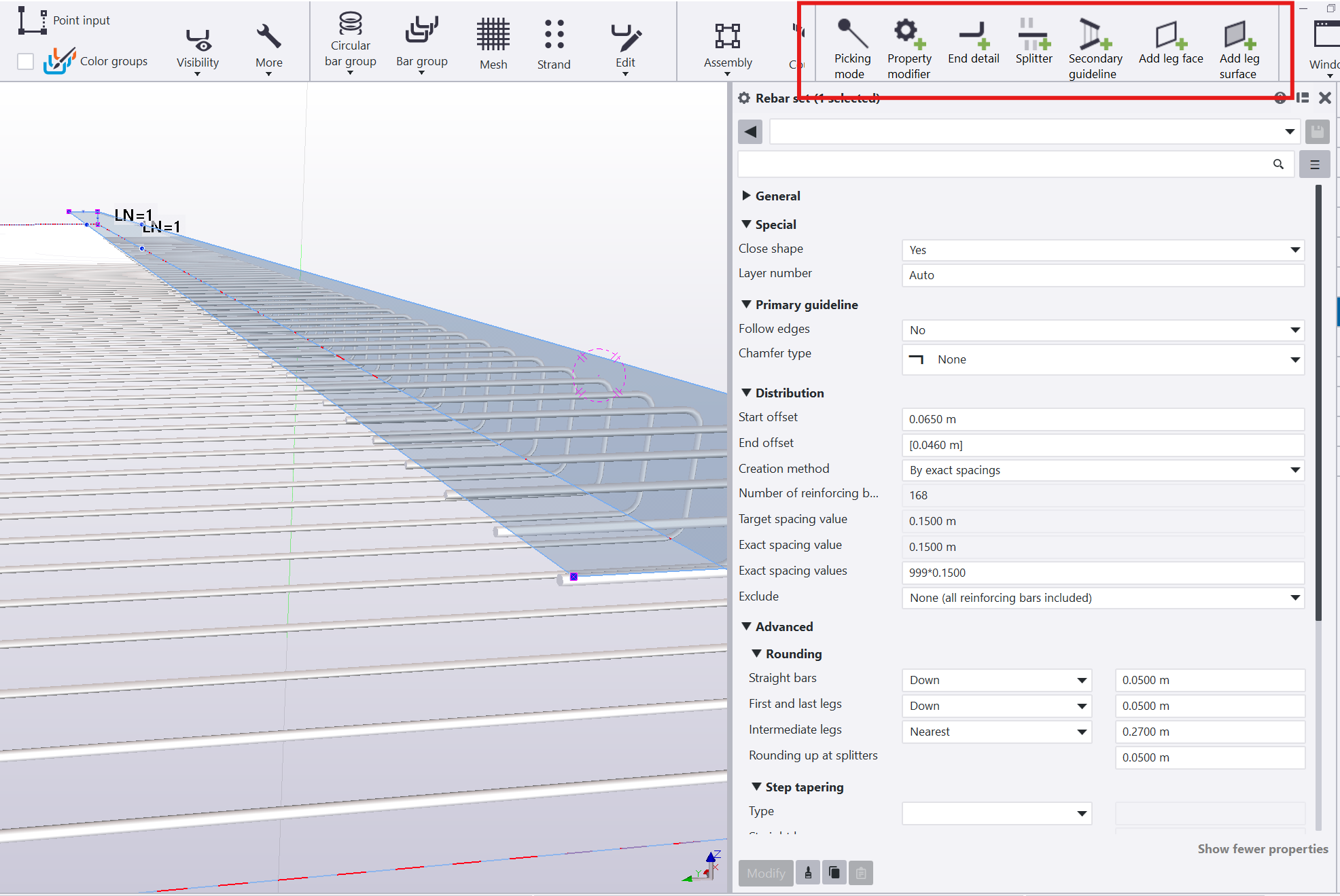
Property modifier overrides properties such as bar size or spacing for a subset of bars in the set, without affecting the rest.
- End detail modifier acts on the nearest end of the bars it touches, adding hooks or cranks, or defining length adjustments and end preparations, at that specific location. Hook shape, angle, radius, length, and rotation out of the bar plane can be set per modifier, and how many bars at that location are affected, and which one is first, can be limited rather than applying to every bar in the set.
- Splitter splits bars in a rebar set into shorter lengths and creates a lap or crank splice at the split. Lap and crank dimensions can be read automatically from standard, code-based calculations tied to bar size, or driven by a manufacturer-specific stock and lap length table, with a fallback setting for grades or sizes that aren’t listed. That means a splitter can be used specifically to keep split bars within an actual available stock length rather than an arbitrary cut. Bars can also be bundled by number at the splitter, and any extra length is handled directly there.
- Secondary guideline allows a different spacing to be defined at the start and end of the same rebar set, useful where spacing needs to transition along a member rather than stay constant.
Taken together, this is what makes it practical to keep bar spacing, cover, and end conditions correct across a large repetitive structure, including its non-repetitive spots, without manually placing and checking every bar.
Checking before export. Modeling correctly and exporting correctly are connected by a checking stage that’s easy to skip under schedule pressure. Production exports depend on up-to-date numbering. PXML export, for example, only works on numbered objects and will flag it if numbering is out of date, so re-running numbering after late geometry changes isn’t optional housekeeping, it’s a precondition for the export being trustworthy. Organizer can be used to group and track reinforcement by status as it moves from modeled to checked to released, and reports generated directly from the current model let quantities, marks, and schedules be verified against what’s actually there before anything is issued, rather than trusting a schedule produced earlier in the process.
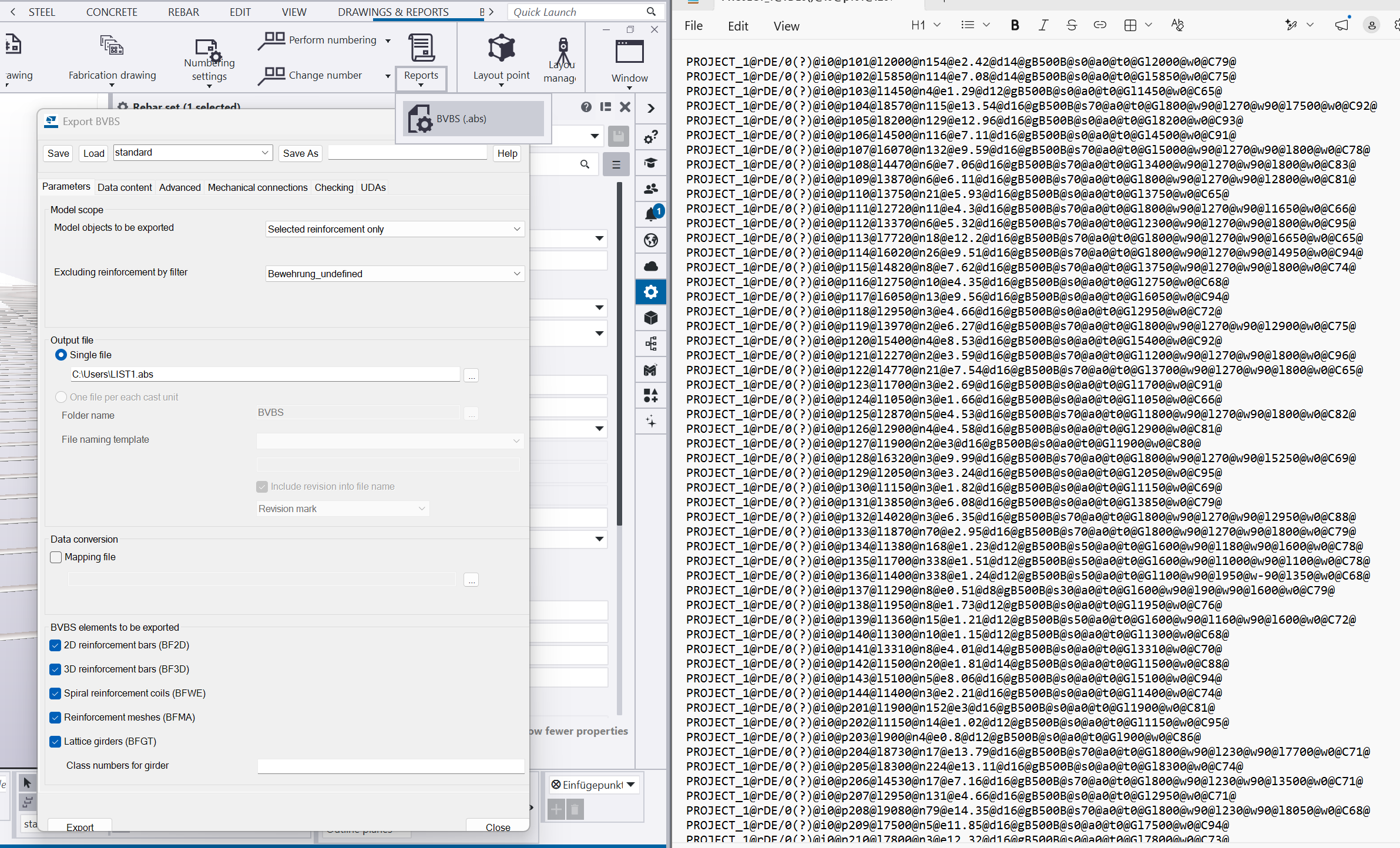
Export to BVBS (.abs). Tekla Structures can export reinforcement geometry in the Bundesvereinigung Bausoftware (BVBS) format, producing an ASCII text file with the .abs extension. The supported version is BVBS 2.0 from 2000; Tekla Structures versions from 2021 onward also support BVBS 3.0 from 2018, which follows the same syntax as 2.0 but adds support for coupler and thread data. The export covers bent reinforcing bars, reinforcing bar groups, and reinforcement meshes, rectangular or polygonal, bent or non-bent, and may include cuts, with export of hooks also supported. Because the export works from the actual modeled bar geometry, the values that reach the fabrication machine are the same ones present in the model, provided that geometry was defined precisely enough in the first place, which is the whole point of fabrication-readiness. For formats outside BVBS, a separate Rebar Export extension (available through Tekla Warehouse) can output to aSa or Soule-type files instead, which is relevant where a shop or region standardizes on one of those.
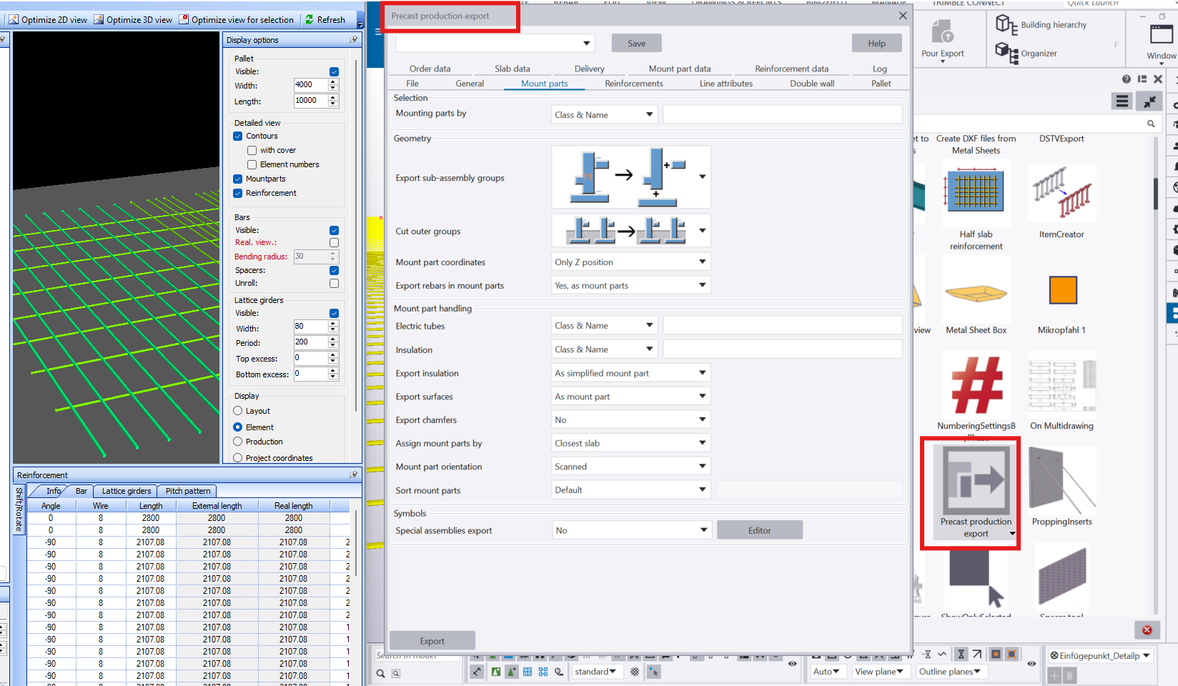
Export to PXML for precast production. For precast work, the Precast Production Export extension (from Tekla Warehouse) supports export to PXML (Progress XML), a format developed by Progress Software Development for exchanging data between design software and precast factory systems, specifically the production control/management systems ebos, erpbos, and ProFit, along with the AviCAD viewer. PXML carries both the product geometry and related production/ERP attribute data for concrete elements, embeds, and reinforcement, and, like BVBS, the export only runs against numbered objects. This matters for reinforcement specifically because precast production planning depends on the same fabrication-level precision described earlier: a PXML export inherits whatever level of detail and consistency exists in the source model.
PDF export for drawings and schedules. Not every deliverable needs to reach a machine directly. Reinforcement drawings and bar schedules generated in Tekla Structures can be exported as PDF for review, approval, and distribution to people rather than equipment: engineers checking a schedule, a site team confirming a delivery, or a fabricator without a direct machine-format integration. PDF export doesn’t add or check precision the way a BVBS or PXML export effectively does by virtue of feeding a machine directly. It’s only as accurate as the model and schedule it was generated from, which is why the underlying modeling discipline still matters even when the deliverable is a document rather than a machine file.
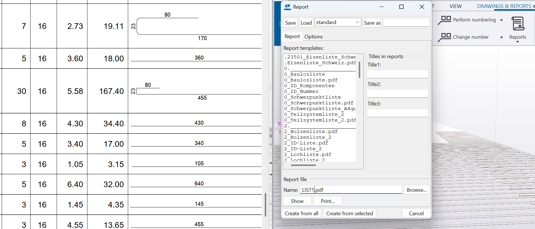
Common Signs a Reinforcement Model Isn’t Fabrication-Ready
Bars modeled without considering fabrication and transport limitations. Long theoretical bars may need to be split and connected with laps or couplers, while bends, hooks, and end conditions must be represented with realistic fabrication geometry.
Bend shapes that don’t match standard fabrication shape codes. A bend that’s geometrically valid but doesn’t correspond to a shape a bending machine or shop crew can produce efficiently creates avoidable delay and cost.
Congestion left unresolved at complex zones. Openings, corners, and connection zones are where clashes between reinforcement, embeds, and formwork are most likely, and where “it fits in the model” doesn’t guarantee it fits in the actual pour.
Schedules generated before the model was finalized. Any bar schedule needs to be regenerated after geometry changes; a stale schedule circulating alongside an updated model is a common source of field errors.
Marking inconsistency across similar-but-not-identical bars. Two bars that look the same in an isometric view but differ slightly in length or bend location need distinct marks. Treating them as interchangeable is where bundling errors on site usually start.
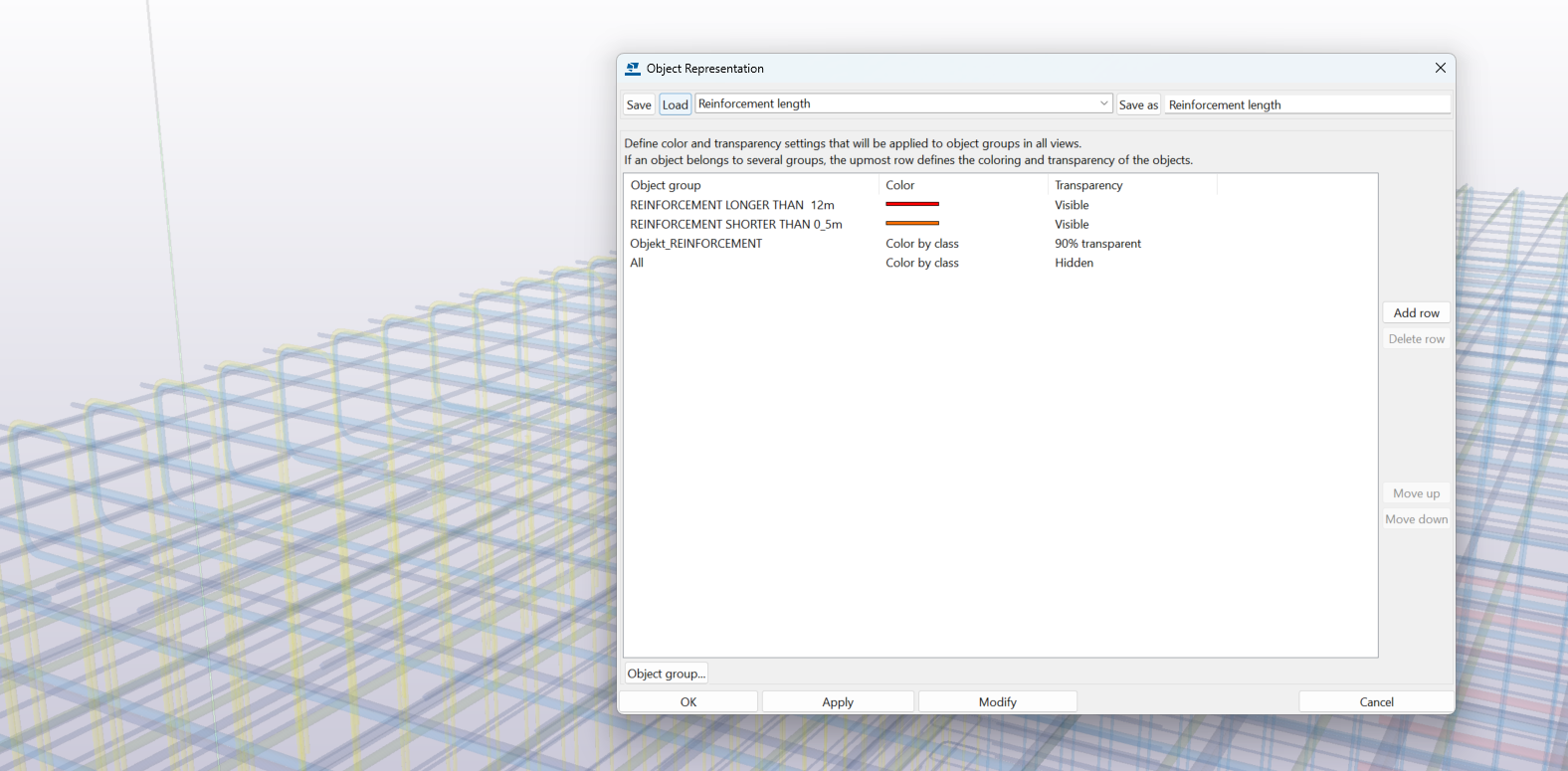
Custom filters and object representation settings can be used to speed up model checking by visually highlighting reinforcement that meets specific criteria.
Best Practices Checklist
- Verify every bend in the model against realistic fabrication geometry, not just visual correctness.
- Model laps and splices explicitly wherever bar length, construction joints, or sequencing require them.
- Build cover and clearance into the geometry itself, especially at congested or non-typical zones.
- Regenerate schedules directly from the current model state before they’re issued.
- Organize bar identification around the actual construction sequence, not just internal model structure.
- Treat any bar shape that doesn’t correspond to a standard, fabricable geometry as unresolved, not as a detail to fix later.
Conclusion
A reinforcement model being structurally correct and being fabrication-ready are related but different standards, and the difference isn’t cosmetic. Fabrication-readiness means every bar in the model is defined precisely enough, in shape, length, cover, and identification, that it can move directly into cutting, bending, and site delivery without someone downstream having to interpret or correct it. The earlier that standard is applied, the less rework shows up at the point where it’s most expensive to fix: on the shop floor or on site, rather than on screen.
FAQ
Q: Isn’t a reinforcement model that satisfies the structural design automatically ready for fabrication?
A: Not necessarily. Structural adequacy addresses whether there’s enough steel placed correctly to meet the design. Fabrication-readiness addresses whether every bar’s shape, length, cover, and identification are defined precisely enough to be cut, bent, and delivered without further interpretation. A model can meet the first standard while still falling short of the second.
Q: What’s a common cause of fabrication errors traced back to the model?
A: Inconsistencies between what the model shows and what the bar schedule says, usually because the schedule was generated before a late geometry change, or because two similar bars were left sharing a mark despite differing in length or bend location.
Q: Does fabrication-readiness mean modeling every bar in more detail than necessary?
A: No. It means modeling the details that actually affect production and buildability (bend geometry, cover, laps, identification) rather than adding detail indiscriminately. A model can be fabrication-ready without being more complex than it needs to be.
Q: Is “ABS” a separate rebar standard from BVBS?
A: No. .abs is simply the file extension used by Tekla Structures’ BVBS export. BVBS is the underlying standard; the .abs file is its output format.
Q: What’s PXML used for, and is it the same as a rebar-specific export?
A: PXML (Progress XML) is a precast production format, exported through a separate Precast Production Export extension. It carries both geometry and production/ERP data from Tekla Structures to precast factory systems, and reinforcement is just one part of what it can carry. It isn’t a substitute for a dedicated rebar fabrication export like BVBS when the work isn’t part of a precast production workflow.